Andrew, AudioSan, 6L6 and others,
Thanks for attempting to help me out here.
6L6 noted that:
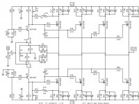
"The short story is that the compensation cap from gate to output (marked as C2 on the output boards, but marked as C3 and C4 on the V3 schematic) need to be used. 1000pF is working well."
I have attached Nelson's V3 schematic. I haven't seen the schematic of the board that 6L6 is using, but have seen the photos of the board. Evidently, C2 on that board is acting as C3 and C4 on the V3 schematic I attached.
6L6, please correct me on this. Is there one C2 on the board you are using that can replace both C3 and C4 on the schematic? This doesn't seem correct to my understanding, but I am normally pretty confused. Might you post a link to the schematic (maybe you did and I missed it. If so, sorry).
Regardless, I am attempting to understand whether C3 and C4 on the V3 schematic (attached), and thus, C2 on 6L6's board, are simply passing high frequency AC back through the feedback circuit to dampen the high frequency oscillations that were contributing to 6L6's repeated loss of MOSFETs, or whether there is some other action of these components. And I was interested in what frequency range might be passing through the capacitors, which would imply what frequency range was responsible for overload and loss of the MOSFETs.
Nelson wrote:
"Depending on layout and other little issues, we might ultimately have to consider using capacitors to perform frequency compensation which have been absent (along with coupling capacitors) in previous F5 versions. In actual testing I found that ringing and oscillation issues can be dealt with by optional C3 and C4 in values ranging around 1 nF. An alternate location where compensation can be performed is capacitance of similar value across the feedback resistors R7 and R10. I did not encounter oscillation, but at these bandwidths we are working near the edges, so it's a possibility."
Steve
Thanks for attempting to help me out here.
6L6 noted that:
"The short story is that the compensation cap from gate to output (marked as C2 on the output boards, but marked as C3 and C4 on the V3 schematic) need to be used. 1000pF is working well."
I have attached Nelson's V3 schematic. I haven't seen the schematic of the board that 6L6 is using, but have seen the photos of the board. Evidently, C2 on that board is acting as C3 and C4 on the V3 schematic I attached.
6L6, please correct me on this. Is there one C2 on the board you are using that can replace both C3 and C4 on the schematic? This doesn't seem correct to my understanding, but I am normally pretty confused. Might you post a link to the schematic (maybe you did and I missed it. If so, sorry).
Regardless, I am attempting to understand whether C3 and C4 on the V3 schematic (attached), and thus, C2 on 6L6's board, are simply passing high frequency AC back through the feedback circuit to dampen the high frequency oscillations that were contributing to 6L6's repeated loss of MOSFETs, or whether there is some other action of these components. And I was interested in what frequency range might be passing through the capacitors, which would imply what frequency range was responsible for overload and loss of the MOSFETs.
Nelson wrote:
"Depending on layout and other little issues, we might ultimately have to consider using capacitors to perform frequency compensation which have been absent (along with coupling capacitors) in previous F5 versions. In actual testing I found that ringing and oscillation issues can be dealt with by optional C3 and C4 in values ranging around 1 nF. An alternate location where compensation can be performed is capacitance of similar value across the feedback resistors R7 and R10. I did not encounter oscillation, but at these bandwidths we are working near the edges, so it's a possibility."
Steve
Attachments
At the risk of stating the obvious, looks to me that the compensation caps are needed now because open loop gain has increased a lot due to the paralleled outputs. One thing that might be worth trying (if you wanted to avoid these little caps) is to maybe increase the input jfet source degen resistors to 20 ohms or so. Its a bit of a hassle though because the 220R feedback resistors will also need to be changes to 470-480 ohms.... Anyway just fwiw - great thread btw.
There is one brand of Thermally conductive pad that significantly outperforms 1thou mica.
So far I have not seen any Members posting details of any competitor product that can match Keratherm's Kerafol 86/83.
If the others don't catch up quickly, they can only go broke.
The diyA store now stocks the hard to find Keratherm Red 86/82. I was going to go with the SP2000 from DigiKey (thanks for the data, PKI!) but after reading the EUVL heatsink article and comparing thermal pad specs, the Keratherm looks like a good way to go. Of course, it's the most expensive of the bunch!
BK
There is no doubt that the Keratherm are more capable than the alternatives, but I think it is an over done topic. In reality, a properly mounted fet on mica and thermal grease will do a perfectly good job. a lot of work has to go into getting full potential from Keratherm.
There is no doubt that the Keratherm are more capable than the alternatives, but I think it is an over done topic. In reality, a properly mounted fet on mica and thermal grease will do a perfectly good job. a lot of work has to go into getting full potential from Keratherm.
Work as in heatsink mounting surface smoothness and adequate clamping pressure?
BK
Yes sir. I am not saying that they are not better, but whether or not you will reap great benefit from them. They are quite fragile, TBO, and I have measured very little difference in them vs mica or SP2000.
Thanks for the info. Several good options it seems. As soon as I can get to building I can stop obsessing about the minutia!
BK

")
Hope the builds going well, slowly the parts are ariving for my build.
I was wondering your boards are able to create F5T versions 2 and 3.
im building V2
Was it easy to figure out what to do to build V2 ?
i notice there are a second set of transistors on v3 which wont be used i guess ?
My boards should arrive soon. Cheers
Now time to ask Buzzforb about transistors.
I was wondering your boards are able to create F5T versions 2 and 3.
im building V2
Was it easy to figure out what to do to build V2 ?
i notice there are a second set of transistors on v3 which wont be used i guess ?
My boards should arrive soon. Cheers
Now time to ask Buzzforb about transistors.
Hi to everybody on DIYAudio.
Is long time (I can say years) that I follow this forum and finally I decide to put myself on the game.
I enjoy build ampli from long time, my first ampli was a 20W in classA for car publicated by Bartolomeo Aloia. Was amazing ampli and I built 3 of them with the electronic crossover.
Coming back from the past and stopping to boring all of you...Reading almost all the threats of the PASS forum finally I decide to built a Pass ClassA. Is a hard decision because my work take me around in the word and now I am in Korea that actually is not a good place if you want to be a DIYer. Very nice people but nobody speak english and all the website (digikey and mouser included) are in korean. No way to found a part shop here in Ulsan and I get the address in Seoul (thanks DUG!) but still I don't get the chance to go there (500 km from here).
Reading the guide built of Salomon I contact him for the PCB and he suggest me to look on Jims Audio in ebay. Now I have 2 channels of F5, 2 channels of F5T v3 and 2 channels of AlepX that look very nice
Received the V3 PCB I ordered the 5U 400 chassis from HIFI2000 that look very big and nice but reading this threat I understand that the V3 stereo in one chassis is not the best chance so I thinking come back in V2 using the PCB of V3. The picture of the board is attached. I check the PCB and look exactly as per NP schematic.
Somebody have used already this PCB? I think that can be easly used for the V2 bypassing the cascode and installing 2pr instead of 4pr.
I understand that Buzzforb have a GB for the trasformers and also can provide the Mosfet. May I ask to be part of the GB or is too late?
Any suggestion is of course most welcome!
Thanks to all of you
PS: I mention the picture of PCB... sorry, I will post when I understand how can do...
Last edited:
- Home
- Amplifiers
- Pass Labs
- Building an F5 Turbo v2 (in-Progress)