Well I finally have gotten a new set of output Fets, and the time to get back into this project.
The short story is that the compensation cap from gate to output (marked as C2 on the output boards, but marked as C3 and C4 on the V3 schematic) need to be used. 1000pF is working well.
Also the gate resistors have been increased to 680ohm. These two changes have seemed to keep it stable. Hooray!")
Only one channel up and going right now, the other will be done tomorrow. If everything behaves, I will hopefully have some simple power measurements.
The short story is that the compensation cap from gate to output (marked as C2 on the output boards, but marked as C3 and C4 on the V3 schematic) need to be used. 1000pF is working well.
Also the gate resistors have been increased to 680ohm. These two changes have seemed to keep it stable. Hooray!
Only one channel up and going right now, the other will be done tomorrow. If everything behaves, I will hopefully have some simple power measurements.
Last edited by a moderator:
A few shots of the bench -
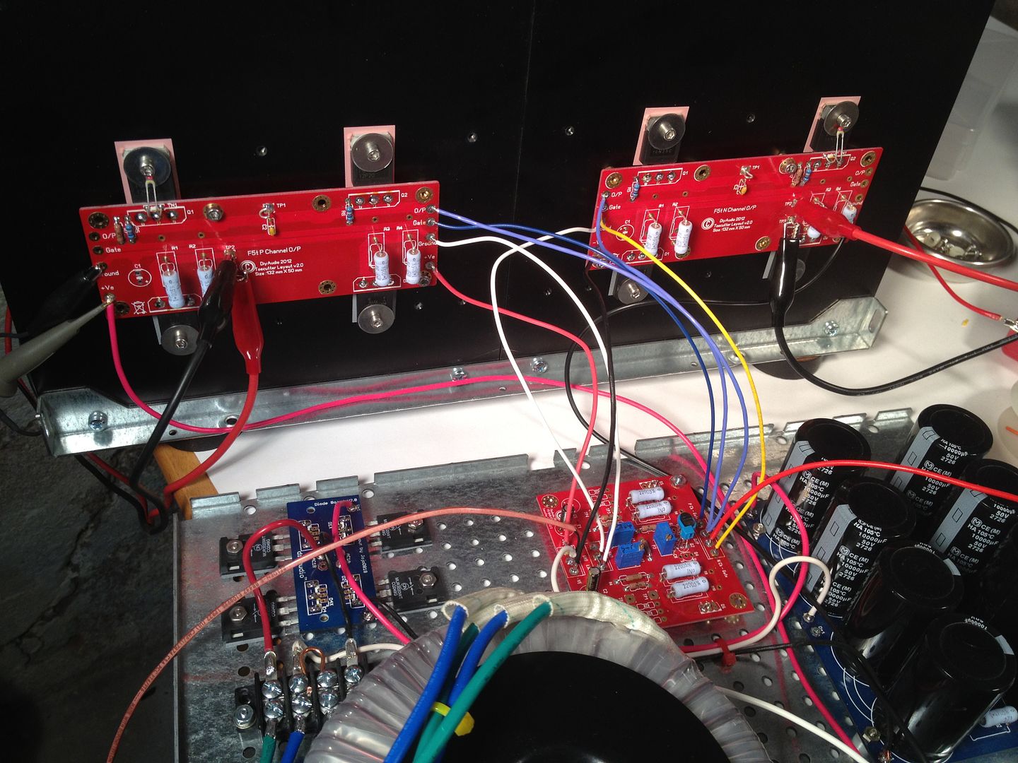
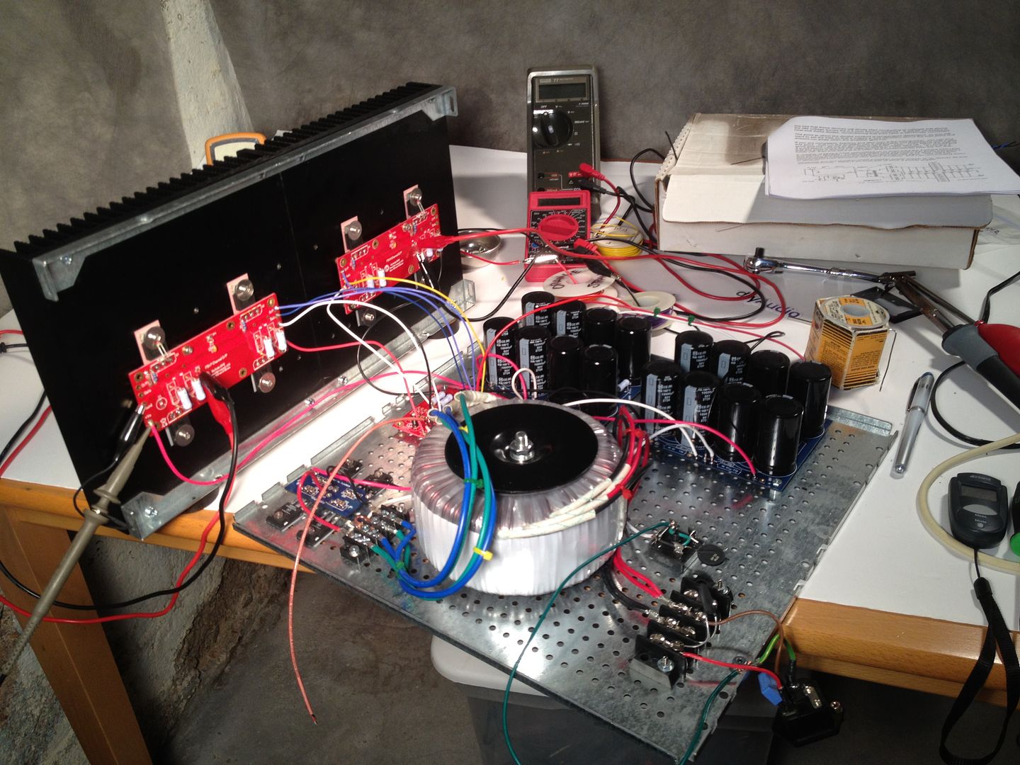
The Front-end board is mounted on the DIY-friendly base because it fits.
Yes, it looks like an explosion at a spaghetti factory - and this is only with one channel... Now I will be the first to mention that I haven't loomed anything together yet, and that will help a bit... but the penality of having the flexibility of the seperate FE board is all the extra wires.
Last edited:
The short story is that the compensation cap from gate to rail (marked as C2 on the output boards, but only on the V3 schematic) need to be used. 1000pF is working well.
.
Looking great! Those are labelled C3 and C4 on the V3 schematic?
Last edited:
The short story is that the compensation cap from gate to output (marked as C2 on the output boards, but marked as C3 and C4 on the V3 schematic) need to be used. 1000pF is working well.
Also the gate resistors have been increased to 680ohm. These two changes have seemed to keep it stable. Hooray!
they need to be used in V2 ? or is that only if theres a stability problem, personal id rather be safe than sorry so perhaps i should follow in your footstep(s).
I can do it anytime now, I just want to modify mounting technic on my 5U chassis, so I will be able do swap amps in no time. It requires some metal work and sanding, just being lazyIf I get a chance, I am gonna hook up the output boards, such that I have 4 output pairs running off single FE board. This will be with standard 47R gate resistors and no cap. fun times.
Indeed, thats why I do not want to mount them on the sink. They will be too close to each other and to the end on the sink(there are two per side). I will mount them on 10mm aluminum bar first and then all these on the sinks. It will help to spread the heat, but I have to prepare surfaces so they make a perfect contact along all the bars.
So yes, 6L6, you say that your amp was blowing outputs because of these oscillations without this cap?
In what I have experienced, yes.
The first time I got it stable was with the 1000pF compensation cap ( marked C3 and C4 in the V3 schematic) and 680ohm gate resistors (R13-16 in the V2 schematic)
How hot do those PSU diodes get out of interest ?
i think ill add the C3, C4 as well as C1, C2. do they have to be bi-polar ?
just a guess maybe wire length is making your amp more susceptible to oscillations.
Btw out of interest which type of caps are preferred by audio freaks ?
i think ill add the C3, C4 as well as C1, C2. do they have to be bi-polar ?
just a guess maybe wire length is making your amp more susceptible to oscillations.
Btw out of interest which type of caps are preferred by audio freaks ?
Last edited:
How hot do those PSU diodes get out of interest ?
10Deg F above ambient. Which is to say barely warm to the touch.
I think ill add the C3, C4
I strongly suggest bigger gate resistors as well.
just a guess maybe wire length is making your amp more susceptible to oscillations ?
Perhaps, but the original test rig had much shorter wire links.
Btw out of interest which type of caps are preferred by audio freaks ?
New stock of the proper value and voltage rating.
I have had very good luck with the Panasonic T-HA series, as well as similar ones from Nichicon and Rubycon.
What kind of matching needed for OT ?
Hi All,
I am seriously following all the Turbo threads but could not find any info on how crucial the matching both between the paralleled N and P is (ok, the closer the better I guess, but...) , and more important if the N should be matched to the P which is more time consuming and last but not least far more costly.
I'd appreciate any help on this matter.
Cheers,
Max
- Home
- Amplifiers
- Pass Labs
- Building an F5 Turbo v2 (in-Progress)