I don't have a full datasheet either, but I can give you some ballpark
information.
Operating the SITs in CS mode and comparing gain vs frequency at different
source impedances, I get an apparent input capacitance of about 1.4 nF
for the SIT-1's and something on the order of 2.5 nF on the 2SK82's. This
seems to be pretty proportional to the chip size / dissipation ratings.
This capacitance would be the sum of Ciss and Crss. When you factor in
the gain in CS mode for different parts and compare, you see that parts
such as the SIT-1, 2SK77B, 2SK92, and the IRFP240 mosfet all end up in
approximately the same ballpark, with the SITs having somewhat less
capacitance.
For thumbnail calculation, you could take the 1300 pf Ciss and 93 pF Crss
of the IRFP240 (150 watt chip) and scale it by wattage. I don't think you
would be far off.
Thank you for your reply.
I'm an old school Lightbox and Track & tape guy so am basically self taught when it comes to the world of computer simulations.
I’m not even sure under what operating conditions the capacitances should be measured, and considering that CDS & CGD are non-linear capacitances and are very much dependent on the Junction voltage – I’m left presuming that the JFET junction should be biased off as with an enhancement mode devices?
With Enhancement mode MOSFET devices the capacitances are normally described:-
Ciss (input capacitance, Drain and Source terminal shorted)
Coss (output capacitance, Gate and Source shorted)
Crss (reverse transfer capacitance, Gate and Source shorted)
So one would presume that we need to bias the JFET device so that its “Switched off” but then how to measure these capacitances with an applied Bias voltage – not with my cheap capacitance meter
Ciss = CGD + CGD
Coss = CGD + CDS
Crss = CGD
I found the first page of the 2SK60 datasheet that claims a Ciss of 190pF, so crudely doubling up the capacitance for the double die 2SK82* gives a Ciss of 280pF – if I only knew the value of Crss then I could simply calculate the others. I am somewhat surprised that for such a power device Ciss is so low… This makes me wonder if its been measured in error as an Enhancement device with an VGS of 0V... (I could believe a Ciss of 1900pF for the 2SK60 which would be closer to your 2500pF for the 2SK82).
*I suspect that the input capacitance of the 2SK82 will be slightly less then twice the 2SK60 as its higher voltage device which will result in a lower Crss…
The poor resolution scan of the 2SK60 datasheet appears to state:-
VDS = -15V & VDS=0V
So I’m guessing it should say VGS = -15V and VDS = 0V.
I have many questions and with so little understanding, I’d like to have a Spice Model of the 2SK82 & 2SJ28 that has values other then zero in these fields – I don’t understand the point of a Spice model with zero for these rather critical device characteristics…
Last edited:
I don’t understand the point of a Spice model with zero for these rather critical device characteristics…
Right, I should have cursed the darkness, instead.
 Merry Christmas, boyz! So long for another year.
Michael,
Please forgive me, my post was not meant as a criticism of your efforts as in fact I've used your models in my simulations and these have helped be greatly with the driver circuit operation - however without the junction capacitances the models are "useless" in determining the amplifiers open and thus closed loop characteristics - this is what I meant to say. Please forgive me for my poor choice of English - I'll never be one for the diplomatic core...
I've struggled today to characterise the VFET's using a leader LCR745G (LCR only upto 1KHz, but with external bias).
What is totally evident (and to be expected) is that both Vgs & Vds has a massive impact on the Junction capacitances - the device behaving like a varcap diode
My current Spice properties for the 2SK82
*PROPERTIES,10
CDS=42p
CGD=142p
CGS=319p
K=0.157
MU=7.3
N=2.24
POL=1
RG=2MEG
VCT=0.0
X=1.51
These are based upon my crude measurements (which I have no faith in, as I don't understand at which "Bias" voltage the junction capacitances should be measured for a JFET device - What I'm trying to say is at what operating voltage does Spice "expect" the capacitance Variables CDS, CGD & CGS to be measured on a real device?
I measured (2SK82 KE-33):-
Ciss 461pf (-15V VGS, VDS 0V)
Coss 184pF (-9V VGS, VDS 0V)
Crss 142pF (-9V VGS, VDS 15V)
I used a 9V battery for the "floating" biasing arrangement.
I stress, please don't take these values as correct, I'm still in the process of trying to understand how to correctly measure these devices.
Today I ordered a HP4275A LCR with option 001 internal Bias, to replace the rather Mickey Mouse Leader - but this will not help much until have have a better understanding of what I'm doing.
Last edited:
Also, when looking at the Spice models, with my very limited knowledge of such matters I don't see how the non linear junction capacitances are realistically modelled... measurement with the LCR and external bias voltage demonstrate highly non linear capacitances which if not modelled correctly I cannot see Spice results being realistic?
I presume I'm missing the bigger picture?
I presume I'm missing the bigger picture?
Great Michael is back on forum

 Thanks for wishes Merry Christmas
happened to get two pair of NEC made SIT, 2SK70 and 2SJ20.
Hi Folks.
I happened to get two pair of NEC made SIT, 2SK70 and 2SJ20.
They have bigger Gm and high temp max, 150 deg. C. than the popular Sony 2SK82 and 2SJ28.
Now,I am wanting to build a stereo PP amp using them.
I tried to generate the spice models and completed as a practical model which may fit on 4-8 ohm load-line by the way M. Rothacher presented on UTUBE video and also Audiohobby.com.
As I do not have complete information, I tried to fit it manually.
2SJ20 model has same parameter but opposite polarity.
Capacitances are my best guess.
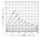
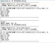
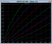
Attached images;
1. 2SK70 Id-Vds data.
2. 2SK20 2SJ20 Spice model for LTSPICE.
3. generated curve by the model.
Hi Folks.
I happened to get two pair of NEC made SIT, 2SK70 and 2SJ20.
They have bigger Gm and high temp max, 150 deg. C. than the popular Sony 2SK82 and 2SJ28.
Now,I am wanting to build a stereo PP amp using them.
I tried to generate the spice models and completed as a practical model which may fit on 4-8 ohm load-line by the way M. Rothacher presented on UTUBE video and also Audiohobby.com.
As I do not have complete information, I tried to fit it manually.
2SJ20 model has same parameter but opposite polarity.
Capacitances are my best guess.
Attached images;
1. 2SK70 Id-Vds data.
2. 2SK20 2SJ20 Spice model for LTSPICE.
3. generated curve by the model.
Attachments
- Status
- This old topic is closed. If you want to reopen this topic, contact a moderator using the "Report Post" button.
- Home
- Amplifiers
- Pass Labs
- Simulating SITs