Hi,
in this single ended classA circuit the lower part is a dynamic current source with 100mA or 200mA idle.
So power consumption of the amp is low.
The voltage follower fet is cascoded by the upper fet.
As we know, voltage follower fets like to conduct current")
1A sounds much better than 100mA
The only little problem is that idle consumption will be 10 times higher
So there is a 6V floating psu connected to the voltage follower fet, this fet will conduct always about 1A current.
The idle current trough the current source & cascode fet is 200mA, while through the voltage follower fet it is 1A
Also the diode of the floating psu will never switch off
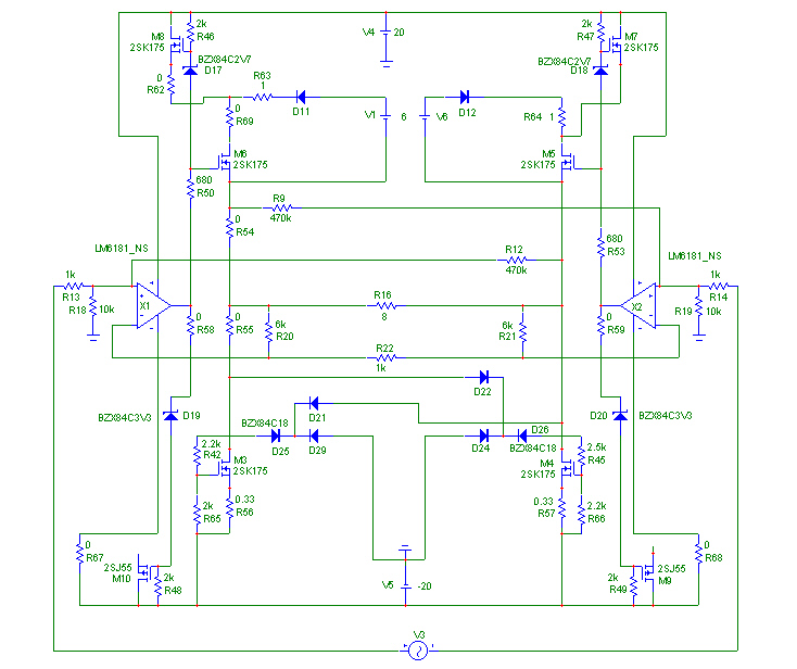
Do not look at the lower part of the circuit, the dynamic current source - quick and dirty - is voltage controlled, I know should be current controlled, no problem.
Also there is a dead part with another fet on both sides, do not look at that...
This works on the sim.
Also the voltage follower fets see a relative low and constant drain source voltage and thus do not need to be paralleled even @ higher output powers.
Any opinions ???
Greetings, Bernhard
in this single ended classA circuit the lower part is a dynamic current source with 100mA or 200mA idle.
So power consumption of the amp is low.
The voltage follower fet is cascoded by the upper fet.
As we know, voltage follower fets like to conduct current
1A sounds much better than 100mA
The only little problem is that idle consumption will be 10 times higher
So there is a 6V floating psu connected to the voltage follower fet, this fet will conduct always about 1A current.
The idle current trough the current source & cascode fet is 200mA, while through the voltage follower fet it is 1A
Also the diode of the floating psu will never switch off
Do not look at the lower part of the circuit, the dynamic current source - quick and dirty - is voltage controlled, I know should be current controlled, no problem.
Also there is a dead part with another fet on both sides, do not look at that...
This works on the sim.
Also the voltage follower fets see a relative low and constant drain source voltage and thus do not need to be paralleled even @ higher output powers.
Any opinions ???
Greetings, Bernhard
The marketing departments of all amplifier companies
would love to be able to claim SE Class A for their output
stages, but when the idle dissipation is less than twice
the rated output, I think we all know that some sort of
comromise has been made, and the lower the dissipation,
the more egregious the claim.
would love to be able to claim SE Class A for their output
stages, but when the idle dissipation is less than twice
the rated output, I think we all know that some sort of
comromise has been made, and the lower the dissipation,
the more egregious the claim.
Hi Bernhard,
If you take it to definition that a class-A amp is something of “No current carrying device is ever cut off”, then when it comes to low idle current, yes a class-A amp is possible. But such an amp will be highly non-linear somewhere and needs lots of feedback to get rid of that non-linearity. Also have a look at this device:
http://www.linear.com/prod/datasheet.html?datasheet=113
Cheers
Hi Piotr,
I know that low idle current is not good.
But in this circuit the idle current is only low for the current source fet and the cascode fet. Both of them do not affect sound.
The idle current for the important voltage follower fet is high instead.
And it will never cut off and it will never go much below 1A or more if one likes...
I will make a drawing tomorrow.
Greetings, Bernhard
Quite some time ago the audio community seems to have
divided Class A into two varieties: "Pure" and "Other".
For many, "Pure" means that the idle dissipation is at least
twice the output rating. Another definition of "Pure" rests on
whether a sine wave output to the load results in a sine wave
current appearing through the gain device(s).
I would say that if you meet both those criteria, you definitely
have "Pure". Arguably, everything else is "Other".
Nelson Pass said:... Another definition of "Pure" rests on
whether a sine wave output to the load results in a sine wave
current appearing through the gain device(s).
Hello Nelson,
A remark here. Many amps rely on the fact that the difference of two quadratic transfer functions is linear: PP tube amps as well as some FET output stages in class-A. So I would state that a pure class-A output stage is something where a sinus input generates a sinus output in a resistive load WITHOUT overall feedback and where no device is ever cut off at max. power output. For this the current through individual devices need not to be necessarily sinusoidal IMHO.
Cheers
error?
Hi bernhard!
The error is that the current of about 1A runs thru the fet back
to the voltage source! Current running out of the +pole must flow
back to the -pole of the 6V voltage source. There is no current left
for the signal to output. This current comes from the upper fet
and is definitely no class A.
Running a gainstage in class A means by definition that the device
never shuts off! So called class AB amps generate 2 heavily
distorted waveforms which are added at output. So if you want
no distortion in your class A device you cannot squeeze more
than double the idle current out of it!
Uli
Pjotr said:A remark here. Many amps rely on the fact that the difference of two quadratic transfer functions is linear: PP tube amps as well as some FET output stages in class-A. So I would state that a pure class-A output stage is something where a sinus input generates a sinus output in a resistive load WITHOUT overall feedback and where no device is ever cut off at max. power output. For this the current through individual devices need not to be necessarily sinusoidal IMHO.Cheers
I would beg to differ. I would not consider a dynamically biased
Class A amp (like the Threshold 800A) a pure Class A amplifier,
although it meets this definition.
The requirement that inidividual gain device currents look like a
sine wave (for a since wave output) is loose enough to cover
the relatively small linearity cancellations occuring in
complementary circuits IMHO.
Nelson Pass said:Quite some time ago the audio community seems to have
divided Class A into two varieties: "Pure" and "Other".
For many, "Pure" means that the idle dissipation is at least
twice the output rating. Another definition of "Pure" rests on
whether a sine wave output to the load results in a sine wave
current appearing through the gain device(s).
I would say that if you meet both those criteria, you definitely
have "Pure". Arguably, everything else is "Other".
Ok, lets forget about wether this is class A per definition or not...
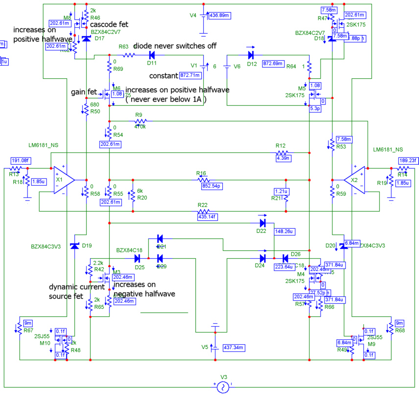
The idle current through the gain fet is 1A, of which 0.2A comes from the cascode fet and 0.8A from the floating psu.
On a positive halfwave the current through the gain fet looks like a positive halfwave and reaches a maximum of 4A, of which 0.8A come from and goto the floating psu, 3.2A come from the cascode fet, 0.2A go to the current source and 3A go to the output.
On a negative halfwave the current through the gain fet will remain 1A, 0.2A come from the cascode fet, 0.8A come from and goto the floating psu, 0.2A goto the current source, the current through the currentsource now looks like a sinus halfwave and at the maximum reaches 3.2A of which 3A come from the output and 0.2A come from the gain fet.
What I see is that there is only one gain device that determines the output voltage.
The current through this device is always between 1A and 4A, in this area fets have good linearity.
All currents never shut of, there is no switching of diodes or fets.
So what I would like to know is, if there is something I miss to see

For my understanding the advantage of SE classA is that there is only one gain device and high current for working in most linear area of gain device.
I still learned a lot here and I am always happy to learn more
Even I could imagin:
As we all know, the first few watts of a SE classA are the best.
Is it because the current varies only little and remains in the linear area?
The higher the output the more current flows in the positive halfwave
, but the less in the negative halfwave and before clipping the current is close to nothing and the gain fet has already left the linear working area.In this circuit there is never less than 1A.
I also could imagine that the fet is happy about less variations in current.
It would also be possible to decrease the current that comes from the floating psu vice versa proportional to the current that comes from the cascode.
I dont want to say that I'm too clever but I would like to hear some striking fact why this will not be good.

Re: error?
there is no current necessary to out put @ idle.
And with signal applied, the positive current comes from the gain fet and the negative comes from the current source.
In Class AB output voltage and current are both shared by two gain devices, but here only currents are shared, the voltage comes from the gain fet only.
uli said:There is no current left
for the signal to output.
there is no current necessary to out put @ idle.And with signal applied, the positive current comes from the gain fet and the negative comes from the current source.
In Class AB output voltage and current are both shared by two gain devices, but here only currents are shared, the voltage comes from the gain fet only.
Nelson Pass said:I would beg to differ. I would not consider a dynamically biased
Class A amp (like the Threshold 800A) a pure Class A amplifier,
although it meets this definition.
The requirement that inidividual gain device currents look like a
sine wave (for a since wave output) is loose enough to cover
the relatively small linearity cancellations occuring in
complementary circuits IMHO.
Maybe I was not clear enough. I certainly don’t mean something like dynamic bias. What I meant is that roughly speaking, the transfer curve of a vacuum tube and lateral power fet’s is more or less quadratic. The combined result of two of them in PP is more or less linear with fixed bias. After all such an amp does need far less feedback.
If these devices were really quadratic they need half the bias current for true class-A of a regular linear device. Something like this:
Attachments
Bernhard said:
The idle current through the gain fet is 1A, of which 0.2A comes from the cascode fet and 0.8A from the floating psu.
On a positive halfwave the current through the gain fet looks like a positive halfwave and reaches a maximum of 4A, of which 0.8A come from and goto the floating psu, 3.2A come from the cascode fet, 0.2A go to the current source and 3A go to the output.
On a negative halfwave the current through the gain fet will remain 1A, 0.2A come from the cascode fet, 0.8A come from and goto the floating psu, 0.2A goto the current source, the current through the currentsource now looks like a sinus halfwave and at the maximum reaches 3.2A of which 3A come from the output and 0.2A come from the gain fet.
What I see is that there is only one gain device that determines the output voltage.
The current through this device is always between 1A and 4A, in this area fets have good linearity.
I still learned a lot here and I am always happy to learn more
As this Fet (constant voltage, constant current) contributes
nothing to gain why not leave it out???
What is the reason to put this fet into the circuit???
IMHO you would achieve better quality without that fet.
Did you build this amp?
Uli
uli said:As this Fet (constant voltage, constant current) contributes
nothing to gain why not leave it out???
What is the reason to put this fet into the circuit???
Did you build this amp?
This fet does not have constant current:
On a positive halfwave the current through the gain fet looks like a positive halfwave and reaches a maximum of 4A
When leaving out the fet, there will be either low idle current through the gain fet, or high dissipation.
I did not build that, as I did not build most of what came to my mind yet
 but it works on the sim.
The joke is that normally you have the high idle current with high dissipation across the whole voltage from + rail to - rail.
In this circuit the high idle current is only across the low voltage floating psu.
What I'm looking for is SE classA sound with low dissipation.
Another idea is to have a custom built transformer with ... -24, -22, ... -10 , 0, 10, ... 22, 24 ... , and switch the psu voltages synchronous with a relais volume attenuator.
Greetings, Bernhard
Bernhard said:
This fet does not have constant current:
When leaving out the fet, there will be either low idle current through the gain fet, or high dissipation.
I did not build that, as I did not build most of what came to my mind yet
The joke is that normally you have the high idle current with high dissipation across the whole voltage from + rail to - rail.
In this circuit the high idle current is only across the low voltage floating psu.
What I'm looking for is SE classA sound with low dissipation.
Another idea is to have a custom built transformer with ... -24, -22, ... -10 , 0, 10, ... 22, 24 ... , and switch the psu voltages synchronous with a relais volume attenuator.
Greetings, Bernhard
Imagine leaving out this particular fet.
You get the same result with less semiconductor in the signal path
The problem is the upper fet not running in class A and this fet
keeps running in class AB with or without that "cascode"
All professional amp builders (like Carver ...) using class G
experience heavy trouble designing away the diode switching
distortion ocurring in circuits like this.
The thing with switched psu is not new either but you encounter
2 problems:
1) when you want that thing fast enough you have to track input
signal and delay the signal until your swiching activity is settled
to the desired voltage, ok you want to track a 20kHz sine wave.
You now can easily calculate the needed swiching speed and
from this calculate the current needed to load the psu caps!
2) You use a different capacitor bank for every tap on your Xfmr.
-> better and cheaper without switching problems is a standard
class A amp.
Btw you never get rid of the intermodulation of the swiching signal
to the audio signal.
Uli
PS: playing around with simulators can lead you in the wrong
direction. build a real circuit from time to time
uli said:
Imagine leaving out this particular fet.
You get the same result with less semiconductor in the signal path
The problem is the upper fet not running in class A and this fet
keeps running in class AB with or without that "cascode"
All professional amp builders (like Carver ...) using class G
experience heavy trouble designing away the diode switching
distortion ocurring in circuits like this.
I do not know what to answer
Look @ the left part of the picture below.
The gain fet is the only part that determines output voltage, so it is single ended, current source is only following and providing negative output current.
And the gain fet works in the most linear region between 1A and 4A.
What else do we want ???
Bernhard said:
I do not know what to answer
Look @ the left part of the picture below.
The gain fet is the only part that determines output voltage, so it is single ended, current source is only following and providing negative output current.
And the gain fet works in the most linear region between 1A and 4A.
What else do we want ???
Bernhard:
Your problem is a naming one:
The real gaindevice is the fet at the top, not the fet which sees
constant voltage across D-S and this fet idles at 0,2A as you
stated. Although it works single ended on a dynamic current sink
it is unfortunately not class A
I am sorry
Uli
uli said:The real gaindevice is the fet at the top
Why ??? Could you explain that more in detail ?
To my understanding the fet on the top is only a supply voltage regulator for the gain fet.
Let the cascode fet deliver a fixed voltage of lets say 12 V...
The current through the cascode fet @ idle remains 200mA, the diode of course switches off.
And the amp clips because the supply is 12V instead of 20V.
So why you think the cascode fet should be the gain device ???
Greetings, Bernhard
- Status
- This old topic is closed. If you want to reopen this topic, contact a moderator using the "Report Post" button.
- Home
- Amplifiers
- Pass Labs
- SE ClassA with low dissipation @ idle - is this it ?