Getting to One Hundred
We've mentioned the utility of the capacitors used in parallel with the source resistors as a means of getting more class A and less distortion (for the same amount of bias. The distortion thing i've described on this thread and others. But today i wanted to look at the dissipation savings.
Ok so i succumbed to a request for 100watts class A into 8R.
You don't see too many of these. Esp not in common source mode. So that begs the question:
Is it a practical thing to try for ? With only 2 paralleled fets for each of the push-pull legs (giving us 4 op fets in total per channel)
Doing some basic math: For 100watts into 8R we would need total bias of 5A or 2.5A per leg (1.25A per fet). The voltage swing needed into 8R is 40V pk and so allowing for losses in the fets I guess lets call the supply rails 48V. This means a standing dissipation per fet of 60 watts - ie No Can Do. I have seen it mentioned many times that the max we can dissipate in the To3 plastic parts is 50 watts if we are to expect decent reliability. Nelson explains here: http://www.diyaudio.com/forums/pass...r-dissipation-turbo-projects.html#post3454347
So here's where the square-law rolls on in to help. Ian Hegglun's articles are a great read (see the WW article and Linear Audio 1) Nelson has also popularised the concept in the F6, F5T and more recently in the vfet amps. Ian's article explains that simply by omitting the source degeneration, we allow the fets to work in square law mode - giving us double the amount of class a power for the same amount of bias. Nelson reports around 70%-80% more class A as opposed to the 100% more suggested theoretically - fets aren't perfect sqr law devices anyhow. My own results were similar to Nelson's.
Ian does away with the source degen by using laterals. Nelson uses diodes or other nice tempco parts such as the semisouth power Jfets or the Vfets. We used caps and I have posted elsewhere the useful effect this has on reducing local feedback around the fets. This time round lets look at power.
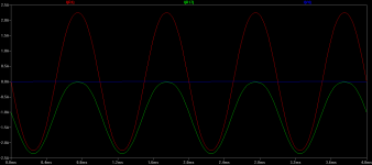
The first sim shows a degenerated op-stage biased at about 1A. The red trace is the current through the load and the green trace is the current through one of the fets. The red trace is showing peaks of 2.25A and at that point the green trace shows that one of the fets is almost shut down with 22mA flowing through it. Its hard calling how-low is zero but I'll just call 22mA as being low enough to zero without having to split picoamps.
This op stage peak current in class A is 2.25A and this is already a bit more than we were expecting with the 2*Iq formula. It just indicates that the 0.47R degeneration used is low enough to still show some sqr law benefits. So this stage gives us 20.25 watts in class A with 1 Amp of bias. In simland of course.
We've mentioned the utility of the capacitors used in parallel with the source resistors as a means of getting more class A and less distortion (for the same amount of bias. The distortion thing i've described on this thread and others. But today i wanted to look at the dissipation savings.
Ok so i succumbed to a request for 100watts class A into 8R.
You don't see too many of these. Esp not in common source mode. So that begs the question:
Is it a practical thing to try for ? With only 2 paralleled fets for each of the push-pull legs (giving us 4 op fets in total per channel)
Doing some basic math: For 100watts into 8R we would need total bias of 5A or 2.5A per leg (1.25A per fet). The voltage swing needed into 8R is 40V pk and so allowing for losses in the fets I guess lets call the supply rails 48V. This means a standing dissipation per fet of 60 watts - ie No Can Do. I have seen it mentioned many times that the max we can dissipate in the To3 plastic parts is 50 watts if we are to expect decent reliability. Nelson explains here: http://www.diyaudio.com/forums/pass...r-dissipation-turbo-projects.html#post3454347
So here's where the square-law rolls on in to help. Ian Hegglun's articles are a great read (see the WW article and Linear Audio 1) Nelson has also popularised the concept in the F6, F5T and more recently in the vfet amps. Ian's article explains that simply by omitting the source degeneration, we allow the fets to work in square law mode - giving us double the amount of class a power for the same amount of bias. Nelson reports around 70%-80% more class A as opposed to the 100% more suggested theoretically - fets aren't perfect sqr law devices anyhow. My own results were similar to Nelson's.
Ian does away with the source degen by using laterals. Nelson uses diodes or other nice tempco parts such as the semisouth power Jfets or the Vfets. We used caps and I have posted elsewhere the useful effect this has on reducing local feedback around the fets. This time round lets look at power.
The first sim shows a degenerated op-stage biased at about 1A. The red trace is the current through the load and the green trace is the current through one of the fets. The red trace is showing peaks of 2.25A and at that point the green trace shows that one of the fets is almost shut down with 22mA flowing through it. Its hard calling how-low is zero but I'll just call 22mA as being low enough to zero without having to split picoamps.
This op stage peak current in class A is 2.25A and this is already a bit more than we were expecting with the 2*Iq formula. It just indicates that the 0.47R degeneration used is low enough to still show some sqr law benefits. So this stage gives us 20.25 watts in class A with 1 Amp of bias. In simland of course.
Attachments
Last edited:
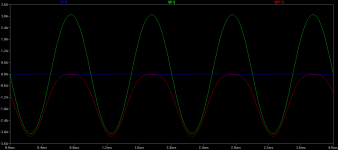
So what sort of improvement can we expect with no source degeneration? Here is the same op stage again at 1A bias. Now we find that the output stage can reach peaks of 3.1A before the other trace gets to the 22mA threshold we defined as shutdown above. So now we get 38.4 watts for the same 1A bias we used earlier. So that's a 89% improvement.....marvelous....
Which means that 100 watts is maybe do-able after all. If I drop the bias in my amp to 1A per fet for a total of 4A i'd get Class A operation of 64 watts with degeneration and somewhere between 115-120 watts with no degeneration. Perfect
BTW the 48Watts per fet is still a massive amount of heat but the IXYS part i selected seems like it will do the job. With some massive heatsinks helping of course. And maybe the weather also
The IXYS ixtq36N30 is rated at 300W. A low junction-case Rth spec of 0.42 C/W provides comfort that this is valid spec. With another 1 C/W conservatively for the fet-heatsink interface and a 50 degree sink, we are looking at junction temps of about 1.42*48 + 50 = 119 degrees. Sure that is borderline insanity versus the speced 150C max. But it is just "this-side" of the border and maybe with some spit n polish on the sinks (and keratherms) I can get the temp down a bit more. But it won't blow to bits that's for sure.
Attachments
Last edited:
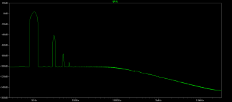
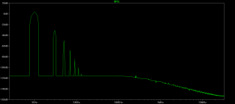
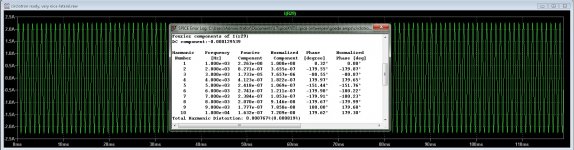
Good looking harmonic spectra. The main problem with caps across the source resistors in at low frequencies since Z = 1/(2*PI*f*C). If you are wanting Z<0R1 at 40Hz, this requires C=0.04 Farad, whih is a factor of about 3 greater than in your schematic of post #70. This suggests that the Valorious might be best accompanied with subwoofer driven by a class-D amp (or something appropriate for the subwoofer). If the crossover frequency was chosen to be 120Hz, that would provide Zmax=0R1 at 120Hz with C=2 x 0.0068F.
One would think so lhquam, but this looks like one of those thing we fret about a lot but that ends up not not mattering much in practice.
We can see *some* effects in the open loop gain plot but once the loop is closed the response is flat as a pancake down to 20Hz where i measured.
When you listen to the amp with/without the caps its pretty clear which one is the winner (well to me at least)!
We can see *some* effects in the open loop gain plot but once the loop is closed the response is flat as a pancake down to 20Hz where i measured.
When you listen to the amp with/without the caps its pretty clear which one is the winner (well to me at least)!
Last edited:
Input Impedance
Chaps - a question from me this time. What sorts of input impedance do you think would be reasonable for amplifiers these days. I know that 47k and upwards are ideal and 1k is too low. But IIRC at one time, many amps had an input impedance of a few K.
I've taken a look at the pre-amp reviews on Sphile and doesn't look to me that any of them would have problems with a 5-10k load....
So is an honest 5-10k amplifier input impedance spec. reasonable you think (esp if its flat across the band) ?
Thanks for your PM Kasey
what is the role of capacitor 6800uf ?
http://www.diyaudio.com/forums/atta...ation-pass-inspired-ideas-val-etchasketch.jpg
Thanks
what is the role of capacitor 6800uf ?
http://www.diyaudio.com/forums/atta...ation-pass-inspired-ideas-val-etchasketch.jpg
Thanks
the caps bypass the source resistor for AC. two main benefits (three for me coz i think it sounds better with the caps..)
i. about 80% more class A power for the same amount of bias with the cap bypass vs without caps. this is because we get more square law transfer function.
ii. eliminate locally generated harmonics caused by the local degeneration. (ok so these two are related..)
posts 141-143 has some info on this.
i. about 80% more class A power for the same amount of bias with the cap bypass vs without caps. this is because we get more square law transfer function.
ii. eliminate locally generated harmonics caused by the local degeneration. (ok so these two are related..)
posts 141-143 has some info on this.
Nice tread, Kasey, your amplifier is indeed very simple, I was busy with help of Alex who is talented to get a autobias working, it is not that easy but the canceling effects of a circlotron do help a lot.
I have here the distorting of mine design, with class ab idle current, from 500 mA the verticals do nice.
regards
I have here the distorting of mine design, with class ab idle current, from 500 mA the verticals do nice.
regards
Attachments
- Status
- This old topic is closed. If you want to reopen this topic, contact a moderator using the "Report Post" button.
- Home
- Amplifiers
- Pass Labs
- The Valorous Amp - A modest aggregation of pass inspired ideas