If you do not find them in you lab I could have a look in mine and borrow you some. I think I am to busy and not experienced enough for audio applications ;-)
That's thoughtful, thanks. I haven't actually looked yet, so let's wait and see.
")
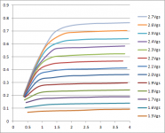
I ran the Id up a little higher but I did not go as far as I wanted before I ran out of time... I made a few measurements up 20Vds and did not see much difference. This graph is with a .25 ohm Rs in the circuit (included in the Vds).
I have a question now for SemiSouthFan: In your paper "is it Semisouth?" you show a graph of Vgs vs Ids of 3 SS devices and a BJT I think. You elude to the device on the left (the lowest Vgsth) actually being out of spec but you say it shows the more triode like behaviour? I do not see this behaviour? Is it that my sample has a Higher than typ Vgsth? Thx
I have a question now for SemiSouthFan: In your paper "is it Semisouth?" you show a graph of Vgs vs Ids of 3 SS devices and a BJT I think. You elude to the device on the left (the lowest Vgsth) actually being out of spec but you say it shows the more triode like behaviour? I do not see this behaviour? Is it that my sample has a Higher than typ Vgsth? Thx
Attachments
I ran the Id up a little higher but I did not go as far as I wanted before I ran out of time... I made a few measurements up 20Vds and did not see much difference. This graph is with a .25 ohm Rs in the circuit (included in the Vds).
I have a question now for SemiSouthFan: In your paper "is it Semisouth?" you show a graph of Vgs vs Ids of 3 SS devices and a BJT I think. You elude to the device on the left (the lowest Vgsth) actually being out of spec but you say it shows the more triode like behaviour? I do not see this behaviour? Is it that my sample has a Higher than typ Vgsth? Thx
This device was out of spec because the threshold voltage was below 0.75 V; but I think it still blocked 1200 V at VGS = 0. And yes the output curves had more shape (lower drain resistance) than the typical R100 with threshold within the limits (0.75-1.25 V). I'll see if I can find it at home.
I think the curves you are seeing are typical for the specified threshold voltage range. I'm not sure why you have Rs in the circuit, as it will influence the shape of the curves you measure.
As far as why I did some curves with an Rs in them. I did a standard style curve a few pages ago without any Rs. ZM suggested I add an Rs and I thought it would be interesting to see the linearization vs loss of gain. Effects of THD in these 2 configurations would have also been interesting but I am not set-up to do such tests at the moment. I suppose I can check my other devices and see if I have a low Vgs device similar to yours.
I'm also interested in looking at an R085 device as to me it sounds more promissing?
I'm also interested in looking at an R085 device as to me it sounds more promissing?
As far as why I did some curves with an Rs in them. I did a standard style curve a few pages ago without any Rs. ZM suggested I add an Rs and I thought it would be interesting to see the linearization vs loss of gain. Effects of THD in these 2 configurations would have also been interesting but I am not set-up to do such tests at the moment. I suppose I can check my other devices and see if I have a low Vgs device similar to yours.
I'm also interested in looking at an R085 device as to me it sounds more promissing?
That's a good reason to add Rs, cause that's what it's supposed to do.
The output curves of the R085 I've been testing in the lab (and R045) have lots of curvature, so you may be right.
I understand the Drain impeadance is much lower in R085! A characteristic similar to those Hollow State devices among others such as SITs
Yep
What's the Buzz? Part I
I've been working on this for awhile. Time to shoot the engineer and post the article!
Attached is the first part in a three part series entitled "What's the Buzz?" It's my attempt to understand why you guys like the SemiSouth JFET so much. I can guess that some of you might think I could better use my time if I did less calculating and more building, but Jim and I are working on that omission. And, you can't take the professor out of me. I just can't help myself, I have to analyze this stuff to satisfy my curiosity.
As before, I hope you find it both worthwhile and entertaining to read. Let me know what you really think!
Attachments
Thanks Dr. Mazzola for a great article and analyses therein.How does it sound
buzzforb, and others. The last page of the article shows that Dr. Mazzola's Company "maintains inventory" of SemiSouth SIC JFETs and other specialty SemiSouth JFETs [maybe SIT?]. Great news.
working my way thru this great writeup - meantime, two q)
a) is this part of the article correct : ? "A trend line analysis performed in the Excel Chart shows good correlation to a cubic law (R2 = 1.00, where perfect correlation is R2 = 1)." .... Presumably the R2 is less than 1.00 since perfect corr is 1.
b) I am probably missing the point, but why the extensive discussion/charts on the 2SC4004 BJT linearity and load-line cancellation instead of doing same on the SJEPs ?
Thanks again
working my way thru this great writeup - meantime, two q)
a) is this part of the article correct : ? "A trend line analysis performed in the Excel Chart shows good correlation to a cubic law (R2 = 1.00, where perfect correlation is R2 = 1)." .... Presumably the R2 is less than 1.00 since perfect corr is 1.
b) I am probably missing the point, but why the extensive discussion/charts on the 2SC4004 BJT linearity and load-line cancellation instead of doing same on the SJEPs ?
Thanks again
Thanks for the kind comment.
(a) Good question! I figured somebody would (and should) ask. The actual R^2 is less than one, but not by much. Excel rounded 0.999... to 1.00 when I fixed the number of decimal places to report. So, to answer your question, R^2 = 1 is indeed perfect correlation. R^2 = 1.00 is simply rounding up a number very close to 1.
As for (b), great question given the thread, and worthy of an appropriate answer. I'll make two comments and then let you decide if you would like more clarification.
First, I think a "linear" transistor as a concept is worth discussing, and if one reveals itself in its transfer characteristic, like the 2SC4004, better to talk about it to see if we can understand why. Might be of use to the crowd around here. Very inventive bunch.
Second, the 2SC4004 transfer curve is an indicator of what might be done with an R100 with sufficient curvature in the output characteristics that is in series with extra drain resistance that is itself not in parallel with the load. Would a little extra power dissipation allow the drain current THD to be cleaned up without relying solely on the speaker load for canceling, which is not purely resistive? It's another means for output loop feedback than just source degeneration. I discuss this motivation at the end of that section. More analysis would be needed to answer that question than can be done with the commonly available Spice model of the SJEP120R100, which doesn't model the output curvature very well.
Hope this helps clarify my motivation.
Nice, Dr. Mike! I think it will keep the audience busy for at least a day...
Hey, your the man. BTW, a "fat cab" is heading your way.


I have a question about the cubic law component. Like everyone else, I
assume that fets are square law devices, and this is supported by the
clean second harmonics we get when we are only varying the Ids current
with the Vds voltage remaining constant. When Vds is allowed to vary with
signal, we start seeing some 3rd harmonic creeping in, and when the gain
variation due to Drain resistance matches against variation due to
transconductance, we see that "sweet spot" has clean 3rd harmonic with
the second having been cancelled.
Is this related to what you are talking about? Otherwise I'm somehow missing
that in the distortion readings of these devices in ordinary analog use.
even if I read the article in sort of skimp and end fashion ( proper read tomorrow ) , I have some objections :
- there is no enough references neither to Zen Mod nor to Jimi Hendrix's work
- mentioning "and other specialty SemiSouth JFETs" is not for faint-hearted , as I (by very nature ) am

- there is no enough references neither to Zen Mod nor to Jimi Hendrix's work
- mentioning "and other specialty SemiSouth JFETs" is not for faint-hearted , as I (by very nature ) am
I noticed that too ZM. Was trying notnto bring attention to it, but you runied it.
As for the swwet spot, does it always mean second harmonic cancellation. Are we to assume this as the definition. 3rd harmonic is not what i would charcaterize as sweet. ZM, on the other hand
As for the swwet spot, does it always mean second harmonic cancellation. Are we to assume this as the definition. 3rd harmonic is not what i would charcaterize as sweet. ZM, on the other hand
- Status
- This old topic is closed. If you want to reopen this topic, contact a moderator using the "Report Post" button.
- Home
- Amplifiers
- Pass Labs
- SemiSouth boiler room