Great article, and for trouble shooting too. A while ago, Mr. Pass built a Plasma Loudspeaker. I still can see a picture of him next to it. Concern with O3 came up.As promised, attached is the first article entitled "Is it SemiSouth?" This is my attempt to contribute to the understanding of what is inside the TO247 package and how to feel confident that you have a genuine SemiSouth JFET.
I have tried to balance my professor's instinct to bathe you in technical details with my own realization that I would prefer you to find this interesting. Only you will be judge of that, but if it seems a bit corny, please have mercy.
Next up will be an article on what I have learned about the native linearity of SemiSouth JFETs and my personal thoughts on simulation, with the goal of making available relatively simple methods for estimating the performance of SemiSouth JFETs in real circuits.
Best regards.
luckily - all Generg's SS are already tested in vivo
")
that´s my man, exactly.....
4 from Magura, 8 from tea-bag and 8 from Roger combined in endless variations and circuits..... they look like old men, but they are still all working,
Oh, one was lost by failure and two went to a friend for an F2J....
Nevertheless I am very grateful for the article because my DMM measured always nothing and I did not know if I killed one or not... when there was no sound again...
now I can measure with resistors, battery and "billig" DMM following the advice of Semisouthfan these suspect candidates......
 ) - one can augment DMM with one 1V5 cell , polarized properly in series with one of the probes
Power supply/battery approach for diode checking
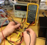
Given the amount of feedback on the DMM approach, I decided to post a picture of me making the same measurement using the power supply approach, this time on a SJEP120R125. In the image you will see my hands probing the gate and source pins of the part and measuring the voltage drop with the Fluke 87. Next to the Fluke is a lab power supply with 8.4 V on the front panel. This simulates nicely a humble 9 V battery which could be used to make the same test. A 2.7 kOhm resistor can be seen suspended by alligator clips between my hands and below the part. The measured forward voltage drop is 2.549 V. I get the same value measured gate to drain for the same power supply voltage and resistor.
The diode checker on this Fluke 87 measured 2.489 V, highlighting what can be seen in the original article, namely, that the forward bias curve of the diode is exponentially rising but still dependent on the exact value of current flowing. The diode checker measured about 7.7 V open circuit voltage.
The bottom line is that diode checkers are not designed for such a high built-in potential. When in doubt, substitute a battery and resistor (a few kiloOhms is perfect) in series with the junction and measure the voltage dropped across the junction.
Attachments
Clever, very clever.considering good common engineering praxis , all those you dropped from the bench on the floor , you can send for proper disposal - to Official PL Disposal Facility
ZM
Official PL Disposal Facility
CEO

Great article, and for trouble shooting too. A while ago, Mr. Pass built a Plasma Loudspeaker. I still can see a picture of him next to it. Concern with O3 came up.
Best regards.
Yep, that devilish OAP (one atmospheric pressure) glow discharge in air will fill a room with O3 if you aren't careful. The well known "Hill Type 1" fixed this problem using Helium. "Fixed," that is, if you think re-ordering a bottle of helium to keep your tweeter running is practical.
But helium, besides controlling the O3, has another crucial advantage. If you read my paper, you'll see what I mean.
My paper was inspired by Alan Hill, whom I had the pleasure of meeting in person and talking plasma speakers with way back when. He told me to look up his patent. I did. It was amazing and the paper I wrote was based on a derivation that he published in the patent. (Most unusual...)
Given the amount of feedback on the DMM approach, I decided to post a picture of me making the same measurement using the power supply approach, this time on a SJEP120R125. In the image you will see my hands probing the gate and source pins of the part and measuring the voltage drop with the Fluke 87. Next to the Fluke is a lab power supply with 8.4 V on the front panel. This simulates nicely a humble 9 V battery which could be used to make the same test. A 2.7 kOhm resistor can be seen suspended by alligator clips between my hands and below the part. The measured forward voltage drop is 2.549 V. I get the same value measured gate to drain for the same power supply voltage and resistor.
The diode checker on this Fluke 87 measured 2.489 V, highlighting what can be seen in the original article, namely, that the forward bias curve of the diode is exponentially rising but still dependent on the exact value of current flowing. The diode checker measured about 7.7 V open circuit voltage.
The bottom line is that diode checkers are not designed for such a high built-in potential. When in doubt, substitute a battery and resistor (a few kiloOhms is perfect) in series with the junction and measure the voltage dropped across the junction.
So, I think here is a solution:
The short circuit currents all of my DMM's only circa 1 mA, in diode check.
If I compute it correctly, in your very nice setup (which is the peak of the electrical engineering sciences) there is about 2 mA.
Am I right?
Ah, it is only now come in my mind, your Fluke 87 has a 7.7V open circuit voltage, what I supposed earlier.
Wacky Gyuri
As Gyuri pointed out, I worked overtime on the design of that circuit.
With respect to the short circuit current, possibly, as it can be an indicator of too low open circuit voltage. Strictly speaking, 1 mA would measure differently by perhaps only a few tens of millivolts. The issue is open-circuit voltage and possibly a threshold condition built into the DMM hardware (speculation). The current available at 2.6 V is much less than 1 mA if the open circuit voltage is around this value. Then the bias current will fall off exponentially and the DMM may shrug it's shoulders (in a manner of speaking) and call it an open circuit.
The short circuit current in my marvel of electrical engineering science is 3.1 mA (8.4 V / 2.7 kOhm). At the measured diode drop of about 2.6 V the bias current was 2.1 mA as you suggest. The difference is that 2.6 V is not a short circuit, but with 8.4 V of open circuit potential, it is not a problem. DMM's commonly have less than about 3 V of open-circuit potential (the designer was expecting 0.7 V or maybe 1 V from an LED). The Fluke 87 is obviously not so limited and while my Fluke 16 worked, the values were more scattered reflecting that it barely had enough open circuit voltage.
I apologize for digressing from the theme. I'll read your paper. The patent by Hill is US 4,219,705. May I introduce you to another Beast. It is an amp by Mr. Pass which he named the "Beast with a Thousand Jfets". Please visit www.firstwatt.com which has its attendant DIY article. Mr. Pass has a large following of students [DIYers] who have built his offering of DIY amps and will continue to do so for years to come. Except; the Jfets used in his Beast are becoming rare and may have the production status of EOL. DIYers would love to get their hands on low cost and equivalent Jfets. I hope that you, and your Industrial position [Co-founder of SemiSouth] can help DIYers with find such fresh supplies. Also, please visit the Thread in the Pass Labs Forum which is entitled " Article: Beast with a Thousand Jfets" for ongoing dialog.Yep, that devilish OAP (one atmospheric pressure) glow discharge in air will fill a room with O3 if you aren't careful. The well known "Hill Type 1" fixed this problem using Helium. "Fixed," that is, if you think re-ordering a bottle of helium to keep your tweeter running is practical.
But helium, besides controlling the O3, has another crucial advantage. If you read my paper, you'll see what I mean.
My paper was inspired by Alan Hill, whom I had the pleasure of meeting in person and talking plasma speakers with way back when. He told me to look up his patent. I did. It was amazing and the paper I wrote was based on a derivation that he published in the patent. (Most unusual...)
Best regards.
Did SemiSouth tank as it was "sole-source"?
The short answer is "no." While that was an issue that came up with some customers, the company was achieving it's goals for large accounts for the SiC transistor. Sales was not the problem. The failure of the company was due to a complex set of factors including operations and financing.
I apologize for digressing from the theme. I'll read your paper. The patent by Hill is US 4,219,705. May I introduce you to another Beast. It is an amp by Mr. Pass which he named the "Beast with a Thousand Jfets". Please visit www.firstwatt.com which has its attendant DIY article. Mr. Pass has a large following of students [DIYers] who have built his offering of DIY amps and will continue to do so for years to come. Except; the Jfets used in his Beast are becoming rare and may have the production status of EOL. DIYers would love to get their hands on low cost and equivalent Jfets. I hope that you, and your Industrial position [Co-founder of SemiSouth] can help DIYers with find such fresh supplies. Also, please visit the Thread in the Pass Labs Forum which is entitled " Article: Beast with a Thousand Jfets" for ongoing dialog.
Best regards.
Thank you Antoinel for your confidence in me.
As you know from my article "Is it a SemiSouth?", I referenced Nelson Pass' Beast paper. I am sufficiently connected to the rest of the SiC transistor community to have an idea of what is coming. I am seeking access to a few parts to see if they have the "right stuff" to be an alternative to the SemiSouth JFET. But the first question that should be asked is, what is it about a SemiSouth JFET that makes it deliver the performance that you and your fellow DIY mates seek? I promise, I have put some thought to that question, originally inspired by Nelson's writings and suggestions on the topic.
As a result, my next article will be a two part discussion on the connection between the terminal properties of a SemiSouth JFET and the circuit performance that audiophiles seek. I will include "DIY Audio" friendly methods for analyzing that connection that I use myself because, frankly, I am no expert in audio amplifier design.
Thank you Dr. Mazzola for replying, and for your correction above which follows from your article. " Thus, every R100 is an example of a “massively parallel” JFET assembly long before Nelson Pass used the term in his latest article “The Beast with a Thousand JFETs” (see http://firstwatt.com/articles.html)."
I look forward to your future articles. Your writing style is clear, educational and entertaining.
Best regards.
I look forward to your future articles. Your writing style is clear, educational and entertaining.
Best regards.
Last edited:
In that regard: Refrences to the Vds vs. Ids from N.P. elude to a triode like behaviour, along with lower Drain impeadance, seem most important and confusing to me. Manipulating the load line to attempt to operate in the most linear region, as triode tube circuits can easily do, see FIRST WATT the F3(or the Zen V9), is understandable but not obtainable in semiconductors so easily. I'm thinking the lower Vds, like the LU1014 part has, can get us closer to that linear transfer curve in your parts also, albeit nwith maybe 6 or 8V? and with loadline canceling performance while deviating from that ideal operating point. This likely would involve cascoding the device but we are fearless DIYers. I live in the New England, electricity is still cheaper than oil. He has also eluded to the 085 device having promise in this rergard also with even lower drain resistance.
Additionally, the input load the signal source sees is a major distortion causing functoin due to the rediculous C curve rising with lower Vds below 50V.
I would think you have all the access you need to papa to learn more of the details. I would bet since you are helping the DIY community so much he would be happy to give you all he knows to help. Give him a call
I should try to find an affordablbe curve tracer myself, 675 was it?
Dr. Mazzola; Mr./Dr. Casady and yourself have joint US patents regarding ICs made with/on SiC which date back to 2002. Is R100 and its manufacture patent-protected? In your article, "Is It a SemiSouth?" of post #2, you dwelled on the possibility of an illegitimate; but functional copy of R100. Thus, your simple and effective test method may not differentiate between them. The ultimate acid test for the DIYer is to drop the devices in an F6 DIY amp. If the impostor device is an NPN BJT, the amp will not speak [or sing softly] because the bias and signal drives [for the base-emitter circuit] are inadequately low. The DIYer and equipment are protected from physical harm. But; if the devices are JFETs, how will a DIYer tell whether they are authentic or copies from the performance of the diy F6 amplifier? This question may be important for some and irrelevant to others.
Best regards
Best regards
In that regard: Refrences to the Vds vs. Ids from N.P. elude to a triode like behaviour, along with lower Drain impeadance, seem most important and confusing to me. Manipulating the load line to attempt to operate in the most linear region, as triode tube circuits can easily do, see FIRST WATT the F3(or the Zen V9), is understandable but not obtainable in semiconductors so easily. I'm thinking the lower Vds, like the LU1014 part has, can get us closer to that linear transfer curve in your parts also, albeit nwith maybe 6 or 8V? and with loadline canceling performance while deviating from that ideal operating point. This likely would involve cascoding the device but we are fearless DIYers. I live in the New England, electricity is still cheaper than oil. He has also eluded to the 085 device having promise in this rergard also with even lower drain resistance.
Additionally, the input load the signal source sees is a major distortion causing functoin due to the rediculous C curve rising with lower Vds below 50V.
I would think you have all the access you need to papa to learn more of the details. I would bet since you are helping the DIY community so much he would be happy to give you all he knows to help. Give him a call
I should try to find an affordablbe curve tracer myself, 675 was it?
Dr. Mazzola; Mr./Dr. Casady and yourself have joint US patents regarding ICs made with/on SiC which date back to 2002. Is R100 and its manufacture patent-protected? In your article, "Is It a SemiSouth?" of post #2, you dwelled on the possibility of an illegitimate; but functional copy of R100. Thus, your simple and effective test method may not differentiate between them. The ultimate acid test for the DIYer is to drop the devices in an F6 DIY amp. If the impostor device is an NPN BJT, the amp will not speak [or sing softly] because the bias and signal drives [for the base-emitter circuit] are inadequately low. The DIYer and equipment are protected from physical harm. But; if the devices are JFETs, how will a DIYer tell whether they are authentic or copies from the performance of the diy F6 amplifier? This question may be important for some and irrelevant to others.
Best regards
I should not be surprised that I have stimulated questions before I laid out my thoughts in a cogent article. That will teach me to post a what-I'm-going-to-do-before-I-do-it post. We'll call it testing the waters. I'm glad you all are interested. And why not? Making an amplifier "sing softly" is what you all do so well. If a SemiSouth JFET helps, then you are by definition interested. If it doesn't help, this should be a thread of one poster (me). Again, we can thank Nelson for bringing to all of us the fact of the usefulness of the SemiSouth JFET for these types of amplifiers. The question of why they are useful is what I want to write about. And in that context, my background as a practicing engineering professional and educator gives me a starting point for my thinking. But, as I said, I am not an amplifier design expert so I will be very upfront in my article to say what I am not considering in the analysis. The reader will need to evaluate this information (and point of view) in the bigger picture, and I see that process has already begun.
But to answer a couple of specific questions:
1. What we need is a simple method to capture the effects of the dependence of Id on both Vgs and Vds, and to make if feasible to allow for part to part variation so that custom models for the specific parts in your inventory can be captured and analyzed with relatively simple hardware and software tools (to include freeware Pspice and spreadsheets) that are within the reach of the DIY community. I'm fortunate to work at a large university and to be using a Tektronix 370B, the cost of which
probably does not qualify as "within reach" unless you are really really serious about your DIY Audio hobby. I will cover that in my article. 2. Yes, the company would have maintained that the R100 is covered by one or more patents. I would look to U.S. Patent No. 6,767,783 as the core patent.
3. In my article, I cast doubt on the likelihood of any SiC part being passed off as a copy of a R100. I do not consider a silicon npn BJT to be a functional copy of a R100, but I will concede that a reader could interpret what I said that way. Sooo, let me say it differently: You can measure the terminal characteristics of each and every SemiSouth JFET in your inventory and prove beyond a shadow of a doubt that it is not a silicon npn BJT. A BJT is not a "copy" of a JFET, but instead it is a fake that has only superficial resemblance to a SemiSouth JFET. If you put a BJT sold as a fake R100 into an F6 I do not know if the BJT would sing well enough to get away with the fraud. Who knows? You might end up liking the BJT better than the SemiSouth JFET! After all, there are a lot of BJTs in the world and they have a significant reputation for linearity. It's an interesting thought, but an altogether different topic.
- Status
- This old topic is closed. If you want to reopen this topic, contact a moderator using the "Report Post" button.
- Home
- Amplifiers
- Pass Labs
- SemiSouth boiler room