btw, there are two ways feedback can be mixed, and two ways it can be sampled; shunt and series. So there are 4 "modes" of feedback;
1) Voltage mixing/Voltage sampling = Series-Shunt fb (like a non-inverting op-amp with gain, and like the F5 amp)
2) Current mixing/Current sampling = Shunt-Series fb
3) Voltage mixing/Current sampling = Series-Series fb (like a current fb amp)
4) Current mixing/Voltage sampling = Shunt-Shunt fb (the Schade-type fb)
It may not seem that Schade fb uses current mixing, but keep in mind that the input voltage is converted to a current via the series input resistor. Ultimately, this form of fb results in a diminished (and mixed average) voltage at the junction of the input and feedback resistors, at the device input.
@SemiSouth, not to rain on your upcoming fb parade, I just thought it an appropriate time to establish the 4 different modes of fb, and particularly, which one relates to the Schade style.")
1) Voltage mixing/Voltage sampling = Series-Shunt fb (like a non-inverting op-amp with gain, and like the F5 amp)
2) Current mixing/Current sampling = Shunt-Series fb
3) Voltage mixing/Current sampling = Series-Series fb (like a current fb amp)
4) Current mixing/Voltage sampling = Shunt-Shunt fb (the Schade-type fb)
It may not seem that Schade fb uses current mixing, but keep in mind that the input voltage is converted to a current via the series input resistor. Ultimately, this form of fb results in a diminished (and mixed average) voltage at the junction of the input and feedback resistors, at the device input.
@SemiSouth, not to rain on your upcoming fb parade, I just thought it an appropriate time to establish the 4 different modes of fb, and particularly, which one relates to the Schade style.
It follows that Schade style negative feedback may have sonic benefits which audiophiles could covet with a cheap semi, and this special sonic attribute is not endowed or possible otherwise by using overall loop feedback, degeneration etc.
My research thus far indicates that the sonic benefit of using little to no degeneration in a common-(e,s,c) stage, is that it preserves the non-linear nature of the device, which results in primarily second harmonic distortion. If you want to linearize an amplifying device (with respect to its output curve spacing), just use a little bit of degeneration.
Shunt-shunt fb (Schade fb) has very little affect on this aspect of the device's linearity(1) (which is good from a sonic perspective), but it goes a long way toward reducing the device's apparent output resistance, and hence reduces distortion caused by non-linear loading.
(1) A device with and without Schade fb produces exactly the same distortion, given the same output voltage swing and into an open load.
Last edited:
Zen Mod, and in a later post Dr. Mazzola commented on this particular graph [Figure 35] in Schade's paper. It is actually 2 superimposed graphs of the plate characteristics of 6L6; before and after applying his inverse-voltage feedback.
The plate characteristic of 6L6 before feedback [intrinsic] is shown in Figs. 20 and 21. It is graphically similar to the drain characteristics of SJEP120R100 which appears in the Box entitled What goes up must come down of Dr. Mazzola' paper "What's the Buzz?-Part II. I know this graph represents the performance of a voltage-variable current source [per Pass].
The plate characteristic of 6L6 after using inverse-voltage feedback is shown in Fig. 34 of Schade's paper. It is similar to the plate characteristic of a triode, and graphically that of SIT which was liberally described by Pass and Rothacher. I know this graph represents the performance of a voltage-variable resistor [per Pass]
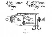
Schade concluded in this powerful and revealing graph of Fig. 35 that "My special style of inverse-voltage feedback [and no other] created the power amp of Fig 33 (c) which performs like that utilizing power triodes instead of tetrodes".
Pass referred in one of his SIT papers that "audiophiles covet the sound of triode tube power amps"; a driver which flared-up the commercial and diy use of SIT. Pass, and DIYer wrenchone have used Schade Feedback in their amps so as to modify the inherent "pentodish" performance of certain semis [MOSFETs, JFETs but not SIT] to that of "triodish". Or a performance conversion a la Schade from a voltage variable current source [plentiful semis] to that of a resitsor [rare SITs].
It follows that Schade style negative feedback may have sonic benefits which audiophiles could covet with a cheap semi, and this special sonic attribute is not endowed or possible otherwise by using overall loop feedback, degeneration etc.
And M. Houston's ZCA has Schade FB so that the Mosfet sounds "triode-like"?
https://picasaweb.google.com/lh/photo/4QjkMa8ot0_xP7SWF06nO9MTjNZETYmyPJy0liipFm0?feat=directlink
Thanks.
M.
My answers to Pop Quiz
Thank you Zen Mod and poynt99 for your posts. Schade showed on page 363 the prospect of reduction in distortion due to his feedback. He quoted a lowered distortion of 0.6% in its second paragraph.
My best answer to the pop quiz is no in each of the 3 amplifiers; because the signature of Schade feedback is absent; meaning there is not a series feedback resistor-capacitor directly connected between the drain and the gate of each semiconductor.
1. diy CSX1 uses SIT which has intrinsic triode properties, and has low drain resistance [my guess 4 Ohms] which dampens [without Schade feedback] the resonant load or loudspeaker's woofer. Pass did not use overall loop, degeneration and Schade feedback in CSX1. He knows whether there is or not a "benefit" in using
Schade Feedback. Separately, I was unable to find a schematic of a Triode power output stage which utilized Schade feedback on purpose.
2. diy F6. A hypothetical Schade feedback path is a series resistor-capacitor from the power output node [absent loop feedback] to only the gate of the bottom JFET. Fits the practice of Schade; but I do not see how to implement it with the upper JFET. Schade feedback in lower JFET is feasible but may destroy the symmetry of operation of output stage. Pass used overall inverse voltage feedback. I read in the previous posts the hint of a Schade negative feedback by proxy of overall or loop negative feedback. Schade had this option in front of him Fig. 33c but ignored to masticate it; still is concept possible?
3. diy F5. Feasible but not implemented using the direct path of Schade Feedback between the power output node and the gate of each output MOSFETs. Its blatant absence may fuel the hypothesis that Overall Loop Feedbackwhich was practiced in diyF5 somehow mediates Schade Feedback in a round about manner. I see forthcoming mathematical equations which blend general feedback theory, u gm, drain resistance etc. to unravel this interesting hypothesis.
nope - there isn't Shade loop there
Agree. The capacitor [33 uf] shorts feedback signal from the drain [wiper of pot] to ground; but provides the essential function of biasing the semi.
Agree. The capacitor [33 uf] shorts feedback signal from the drain [wiper of pot] to ground; but provides the essential function of biasing the semi.
Thanks guys...then I better remove the cap, right?
VDC at the output node is 12V and bias is 1,2VDC; that is 10%FB expectedif I try it.
I am very interested because I plan to swap the Mosfet for the SJEP120R.
M.
Thanks guys...then I better remove the cap, right?
VDC at the output node is 12V and bias is 1,2VDC; that is 10%FB expectedif I try it.
....
M.
don't touch it until you know what you're doing ;
it would be shame to burn any of your speakers ....
"Schade" what?
The listing of the four feedback types in Poynt99's post 401 is correct, i.e., they conform with standard texts on the subject. I tip my hat to him for not making us wait on Part III to clear that up.
Two things I might suggest differently:
1. "Schade" feedback is a term I had never heard of until I started reading this forum. When I looked into where the term came from, I was steered to O.H. Schade's 1938 article that Antoinel has done a remarkable job of digesting. So if that paper (which is six years after Harold Black's famous U.S. patent 2,102,671 was filed covering all forms of negative feedback electronic amplifiers) is the source that coined the term, then examination of Figure 33 of Schade's paper (reproduced in this post) shows that his examples all are Shunt-sampled but Series-mixed. Since I called the Shunt-sampled feedback in my F2J (Nelson's design of course) "Schade Feedback" in Part II, and the AC portion of that feedback is Shunt-sampled Shunt-mixed (Schade, as Poynt99 labels it), I will sheepishly stick my neck out, because I feel like I unintentionally provoked this remarkable explosion of posts, and argue that "Schade Feedback," if it should be so called at all, is Shunt-sampled but mixed either way you like it (like a good Martini, which I'm thinking about having after writing this).
2. Any of the four types of feedback, if linear feedback, will reduce distortion pretty much the same as any other. It depends on the amount of feedback (beta*gain). At least that's what the text book says.
Attachments
To open the discussion up even further, perhaps now is a good time to mention two types of feedback; Local, and Global/Nested.2. Any of the four types of feedback, if linear feedback, will reduce distortion pretty much the same as any other. It depends on the amount of feedback (beta*gain). At least that's what the text book says.
I think when we speak about Schade and his article, he was dealing with local feedback around the amplification device itself. As such, my findings when examining the differences between Schade fb and the fb obtained using local degeneration (both are local feedback), indicate that the results are quite different. In fact, one clear difference is that degeneration increases Ro, while Schade fb decreases Ro. And as I mentioned before, my tests indicate that Schade feedback does nothing to decrease distortion when comparing with equal output voltage swings into an open load. Degeneration on the other hand does decrease distortion under the same conditions of equal output voltage swing into an open load.
To open the discussion up even further, perhaps now is a good time to mention two types of feedback; Local, and Global/Nested.
I think when we speak about Schade and his article, he was dealing with local feedback around the amplification device itself. As such, my findings when examining the differences between Schade fb and the fb obtained using local degeneration (both are local feedback), indicate that the results are quite different. In fact, one clear difference is that degeneration increases Ro, while Schade fb decreases Ro. And as I mentioned before, my tests indicate that Schade feedback does nothing to decrease distortion when comparing with equal output voltage swings into an open load. Degeneration on the other hand does decrease distortion under the same conditions of equal output voltage swing into an open load.
Hello poynt99. Your finding [red in your post] agrees with that of Schade regarding the impact of degeneration; which he mentioned at the bottom of page 363 in his paper. Your mention of the effect by Schade fb and degeneration with load and without it is revealing. The practical value of the no load results is to give a reference or initial conditions to compare with that utilizing usable impedance.
The listing of the four feedback types in Poynt99's post 401 is correct, i.e., they conform with standard texts on the subject. I tip my hat to him for not making us wait on Part III to clear that up.
Two things I might suggest differently:
1. "Schade" feedback is a term I had never heard of until I started reading this forum. When I looked into where the term came from, I was steered to O.H. Schade's 1938 article that Antoinel has done a remarkable job of digesting. So if that paper (which is six years after Harold Black's famous U.S. patent 2,102,671 was filed covering all forms of negative feedback electronic amplifiers) is the source that coined the term, then examination of Figure 33 of Schade's paper (reproduced in this post) shows that his examples all are Shunt-sampled but Series-mixed.
Thanks Dr. Mazzola for highlighting US 2,102,671 which is a reference of 87 pages. Got at PAT2PDF - Free PDF copies of patents: Download and print!.
Harold S. Black has an extensive biography online with a detailed transcript of an interview of his career. Fascinating; this bright scientist also spoke of Bode, Nyquist, Armstrong and his invention of negative feedback. Just search " Biography Harold S. Black". Search likewise for Otto H. Schade. Another interesting scientist with a career, and focus which were different from that of Black. Schade's inverse voltage feedback [e.g. Fig. 33 c in his paper] appeared in the general equivalent schematic of Fig. 1 in Black's patent. Fig. 1 in Black's patent shows negative feedback emanating from the plate of the last vacuum tube [triode] to the grid of the first tube [triode] in the amplifier. Clearly, Fig. 1 of Black's patent will equally apply to negative feedback from the plate to the grid of the same tube which is Schade's inverse-voltage feedback.
Only if the signal is out of phase at the last plate.Fig. 1 in Black's patent shows negative feedback emanating from the plate of the last vacuum tube [triode] to the grid of the first tube [triode] in the amplifier. Clearly, Fig. 1 of Black's patent will equally apply to negative feedback from the plate to the grid of the same tube which is Schade's inverse-voltage feedback.
And this would be global feedback, not local feedback (quite a different animal), which is what Schade's focus was in his paper.
Antoinel, you must have a deep interest in learning more about negative feedback, as revealed by your deep dives into some challenging literature. I wish all of my students had your motivation.
I'm no patent attorney, but I am inclined to agree with you that the way Black (and his attorney) drew the amplifiers is a brilliant example of what is sometimes called a "blue sky patent." In other words, a patent constructed to cover everything the inventor and his legal advice (with perhaps outstanding help from staff at Bell Labs) could anticipate. I think a reasonable expert would agree that this patent taught a circuit with a single gain device or many gain devices, which would cover local or global negative feedback. It is ironic, given the discussion here on what we have been calling "Schade feedback", namely shunt-sampled shunt-mixed (even though Schade drew shunt-sampled series-mixed), that the shunt-sampled shunt-mixed version of an amplifier with "Schade" feedback is clearly drawn as the first figure in Black's patent.
Anyway, Poynt99's point is well taken that in an arbitrary cascade of gain stages the output and the input (however they are defined) must be out of phase for it to be negative feedback. I think that was obvious to Harold Black.
But what stumps me is why it should be a big deal, this local vs. global thing? A good thing to research some more and include in Part III.
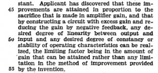
As to the basic relationship between "beta*gain" and distortion reduction irregardless of the type of negative feedback, Harold Black speaks to this in lines 44-55 of page 2 of his patent specification, reproduced below.
As far as I can tell, Harold's assertion is now axiomatic in the electronics engineering educational literature. However, this supposes that the signal who's linearity is being increased is being sampled (directly or indirectly) and compared to the undistorted input by the negative feedback process. If it is not, for example because some other signal is the true "output" as defined by the sampling circuit, then no linearity improvement should be expected. This gets into issues of "observability" etc etc that is covered in the vast literature that now exists and collectively called "modern control theory."
As far as I can tell, Harold's assertion is now axiomatic in the electronics engineering educational literature. However, this supposes that the signal who's linearity is being increased is being sampled (directly or indirectly) and compared to the undistorted input by the negative feedback process. If it is not, for example because some other signal is the true "output" as defined by the sampling circuit, then no linearity improvement should be expected. This gets into issues of "observability" etc etc that is covered in the vast literature that now exists and collectively called "modern control theory."
Attachments
Finally, as to Schade's paper. My impression from reading some of it and scanning much of the rest is that it is a sophisticated and impressive example of what tends to be called in the sales department "sales collateral." The device engineering and the applications engineering people at SemiSouth wrote lots of that, although nothing as comprehensive as Schade's article. What was he trying to help sell? The beam tetrode (i.e., 6L6, KT88, etc.), beloved by so many modern burning amp folks today. The beam tetrode, so anyone can read for themselves by visiting the web, was invented in Europe in the early 1930's but passed to RCA in the U.S., who Schade worked for, to figure out how to manufacture it. By 1938 the fruits of that labor were being pitched to the design community. That's my impression of the intent of O.H. Schade's paper.
So here's another topic for Part III. In the internal workings of an electronic device, like a triode or a tetrode or a pentode or a JFET or a MOSFET, is there a "mixer" where negative feedback is responsible for the shapes of the current and voltage curves we measure at the terminals? And if so, can we implement equivalent negative feedback processes outside of the device in the circuit that the device is connected to? Looking at Figure 35 of Schade's article, what do you think?
P.S. Could Schade's term "inverse feedback" be a not-so-subtle attempt to avoid using the term "negative feedback"? After all, by 1938 Harold Black's patent was in force. Maybe not so far fetched. Here's how Harold Black's patent is described by Edwin Suominen, a registered patent agent: "Fortunately for the analog engineers among us, this fundamental patent and its 126 claims expired in 1954."
(http://www.sos.siena.edu/~aweatherwax/electronics/black_patent.pdf)
just to remind you of can of worms ........ 
there is , besides eternal toob vs. sand hysteria , also eternal one - does triode have internal feedback (comparing to pentode)
not that I care for any of it , or that I'm scared of even slightest possibility of these worms crawling here ...... I just had nice laugh with first morning coffee , remembering numerous occasions of these ...... while I was (still am) blessed knowing how ignorant I am , so not caring .....
...But what stumps me is why it should be a big deal, this local vs. global thing? A good thing to research some more and include in Part III.
Isn't it that Feedback easily lowers low order distortions but, in doing so leaves and/or creates more higher order distortions. Single stage amps generally contain only low order distortion. Multiple stages, with global feedback, effectively multiplies this function generating higher order distortions.
Low order distortion is very tolerable to the listener and generally overshadows the numbers giving a false impression in measurement vs sound quality. Higher order distortions are not acceptable to the listener and although generally at low levels, must be kept to an even lower level to avoid detrimental sound quality.

Indeed there is. That is certain.does triode have internal feedback (comparing to pentode)
It is obvious though, at least I thought?
- Status
- This old topic is closed. If you want to reopen this topic, contact a moderator using the "Report Post" button.
- Home
- Amplifiers
- Pass Labs
- SemiSouth boiler room