R means comma
so 0R1 is 0,1R
0R01 is 0,01R
Thanks ZM
Do they let you out of the Pass forums?

Last edited:
Finally got the diodes!
Happy I won't have to disconnect the speakers terminals anymore when I turn off the amp!
Diode has to be installed in series to limit the current. If it is in parallel, current will be able to go through the resistor & the diode...
I'll get back here when installed to tell the result of this diode installation.
Was pretty $$$ for diodes!
You install either the CRD diode or resistor not both.
Finally got the diodes!
Happy I won't have to disconnect the speakers terminals anymore when I turn off the amp!
Diode has to be installed in series to limit the current. If it is in parallel, current will be able to go through the resistor & the diode...
I'll get back here when installed to tell the result of this diode installation.
Was pretty $$$ for diodes!
With your build, were you able to find 2sc2705's? What are good equivalents?
thanks
Hey Mark Brown, all I've used were BD139 & BD140 all the way. Never even look for matchings. Tazz said they were pretty low in voltage tolerance but never had problem with them. I don't listen to very loud music but I think you should use something with higher voltge tolerance...
O/Ps are Hitachi 2SJ50 & 2SK135.
O/Ps are Hitachi 2SJ50 & 2SK135.
Well hi again all,
Fortunately, one of my "audio friend" just got back to me yesterday saying he has a CT11 and a CT12 (not working) he would sell me for $100. Great ! Just in time!
With the success of my first Mosfet CT12 I'm now at the stage of building my second one and I have a few questions:
I have 2 coroidal transfos with correspondant voltage I took from a "burned" SIMA 300 amplifier for a P.S. start. The question is: What should I use as a bridge rectifier? Shottky diodes? I've red somewhere that faster diodes would not give anything better...
I have 12x 3300 uf "PS audio gold" capacitors I was thinking of putting in series with a .5 ohms resistor between them (3caps on each side). Is this a good idea?
I will use our friend Tazz boards with 241 and 9241 Mosfet (I did use Hitachi J50 an K135 in my first unit which caused me some biasing problem as they are lateral FET). I will build those amp boards with Mr Pass suggested parts and will replace R1 with the current limiting diode which BTW is very good eliminating some "woof" while turning on and off the amp. Not all of tem but most. Anything special I should consider?
Thanks all for your great ideas. My Mosfet CT12 is very very good and since I've paired it with my Mark Levinson ML1 preamp is giving me hours of pleasure!
... I have 2 coroidal transfos ...
Never saw such transformers - I suppose it got something to do with a Greek word κοροιδο ?
If that's so, don't expect much of them....
Pictures
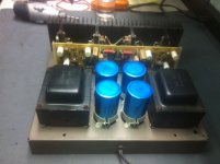
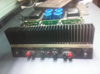
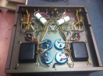
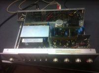
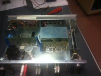
Here are some pictures of my recently acquired CT11 and CT12. I'm almost shy putting the iron on these... They are both completely original, not a single wire moved... Both no rust, corrosion, oxydation, nada... Working like new; not a scratch, pots are clean.. etc...
Here are some pictures of my recently acquired CT11 and CT12. I'm almost shy putting the iron on these... They are both completely original, not a single wire moved... Both no rust, corrosion, oxydation, nada... Working like new; not a scratch, pots are clean.. etc...
Attachments
Hey Electrochap,
this is quite old thread but maybe I have an answer here. I'm using a couple of Tazz board for C12 Mod and Bias setting is always a scaring point for newbie, at leat for me..on your schematic and pcb it seem clear but I would like to be sure:
If I understand Right, At the initial Turn On the screw of the variable resistor R17 must be in COMPLETE COUNTERCLOKWISE position?
This is the schematic. Thank you
Attachments
Hey CUCUclock, actualy I've never built the CT12 with Tazz boards even if I have the whole kit (including the Coroidal trannys, FETs, caps everything) in a box on a shelf ...
The one I've built uses old Hitachi Mosfet (J50, K135) which are laterals and are not biased like IRFs.
If I were you, I would just start at midpoint with a meter watching and adjust wherever you have to go. Slowly. But I'm sure there are way more knowledge people on that Forum (like Tazz and others) who will answer your question knowing exactly where to start... Sorry, I leave this one to others.

To lower the bias current, you'll have to lower the value of R14 to 4k7 (or to 5k by adding another 10k in parallel to R14).
If you want to take out the Vbe multiplier circuit (Q4, R14, R17) and use a single resistor to bias the output stage just put a 1k or 2k multi-turn pot in parallel with C5 instead. Don't forget to set that pot to 0 Ohm before turning the amp on.
Also, check the current through Q3 (should be about 5 mA) by measuring the voltage across R13. If that's so, you'll have the output stage bias at 150-200 mA with pot set at 400-500 Ohms.
it seems the opposite that Mr Pass says.....if I follow him for a project, I can't see why don't follow him on the Bias...
Last edited:
Sure.it seems the opposite ...
The first quote is about the amp version that uses vertical MOSFETs and I was commenting the version with Lateral MOSFETs (k135/j50) in the output stage.
It's easy - if you you use vertical MOSFETs you need Vbe multiplier to control the temperature drift and bias adjusting begins with low/zero current through output stage and, at the start, the pot has to be set to maximal resistance value.
If you decide to use Lateral MOSFETs you don't have to worry about thermal drift so you don't need Vbe multiplier and instead of it, just a single pot between the gates is all you need. With such a configuration the Id adjustment should be started at minimal/zero pot resistance setting.
If you decide to use Lateral MOSFETs you don't have to worry about thermal drift so you don't need Vbe multiplier and instead of it, just a single pot between the gates is all you need. With such a configuration the Id adjustment should be started at minimal/zero pot resistance setting.
it seems the opposite that Mr Pass says.....if I follow him for a project, I can't see why don't follow him on the Bias...
Totally depends on where the pot is.
Collector to Base - go for 0 ohms.
Base to Emitter - maximum ohms.
- Home
- Amplifiers
- Pass Labs
- Pass Citation 12