In preparing to build the F5T V3, I'm finding that it is probably much more effective to build it not only in monoblock format but also with a separate power supply. In order to keep the caps and the transformer from getting really hot due to the amount of heat from the mosfets, separating the main powersupply components from the amp board is is becoming more and more a reality..... Yeah I'm shooting for about 140W @ 8 ohm. ")
There now lies the grounding problem that i've been trying to wrap my head around.
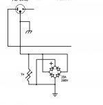
The common "virtual ground" from the power supply needs to be fed to the amp side along with the + and - Vdc. But there is also the case ground for both cases as well as earth ground. How are these connected to the ground scheme?
In a single chassis, case and earth ground is connected AFTER the ground scheme as shown in the picture below. For two chassis, does this mean there is a 4th wire on the umbilical cord that is used just for case ground? If you stack the two cases. will there then be a ground loop?
What about the speaker ground? In a two case scenario, there probably should be some smaller capacitors within the amp case as well. So the virtual ground from the caps I assume will be connected to the -ve terminal of the speaker. Do I just leave this as is since it is attached to the virtual ground of the umbilical?
Any help or confirmation would be appreciated, thanks
There now lies the grounding problem that i've been trying to wrap my head around.
The common "virtual ground" from the power supply needs to be fed to the amp side along with the + and - Vdc. But there is also the case ground for both cases as well as earth ground. How are these connected to the ground scheme?
In a single chassis, case and earth ground is connected AFTER the ground scheme as shown in the picture below. For two chassis, does this mean there is a 4th wire on the umbilical cord that is used just for case ground? If you stack the two cases. will there then be a ground loop?
What about the speaker ground? In a two case scenario, there probably should be some smaller capacitors within the amp case as well. So the virtual ground from the caps I assume will be connected to the -ve terminal of the speaker. Do I just leave this as is since it is attached to the virtual ground of the umbilical?
Any help or confirmation would be appreciated, thanks
Attachments
OK so if I the main C bank in the PSU and some C banks in the amp. I would put the NTC in the amp box and then chassis ground it, and send that through the shield of the umbilical cord and chassis ground the PSU and on to Earth.
Do I have that right?
What would happen if I stack the PSU and Amp (assuming metal on metal)? will that cause a ground loop?
Buzz I'm planing to use SpeakON's they are rated at higher RMS current than PowerCON's... go figure.
Do I have that right?
What would happen if I stack the PSU and Amp (assuming metal on metal)? will that cause a ground loop?
Buzz I'm planing to use SpeakON's they are rated at higher RMS current than PowerCON's... go figure.
Last edited:
OK so if I the main C bank in the PSU and some C banks in the amp. I would put the NTC in the amp box and then chassis ground it, and send that through the shield of the umbilical cord and chassis ground the PSU and on to Earth.
Do I have that right?
What would happen if I stack the PSU and Amp (assuming metal on metal)? will that cause a ground loop?
Buzz I'm planing to use SpeakON's they are rated at higher RMS current than PowerCON's... go figure.[QUOTE.]
They maake higher rated power cons, but in fact, i used speakon as well, as they were cheaper. I rmoved the pressure plate and used screw directly on 14 ga wire.
There is a Thread discussing all the Safety aspects of the separated chassis topology.
There are quite a few unsafe suggestions in that same Thread. You really should go back and read what can go wrong and how easy it can be to become misguided and risk killing unsuspecting operators of your equipment.
Yes, it can be done safely, but do be aware that apparently small discrepancies can open the door to building potentially lethal equipment.
http://www.diyaudio.com/forums/power-supplies/115698-understanding-star-grounding.html#post1403775
The most recent post there was less than a month ago. You could not have looked very far, nor well.
Less than 500 posts. Read them all.
The most recent post there was less than a month ago. You could not have looked very far, nor well.
Less than 500 posts. Read them all.
Pass labs for one does. So I believe if Nelson does it for a living some here could well follow his example in the DIY venue . But that may just be me.No one is building amps with separate power supply chassis?
Pass labs for one does. So I believe if Nelson does it for a living some here could well follow his example in the DIY venue . But that may just be me.
Right, hopefully Mr.Pass will answer this one
.... I can't afford the Xs line to find out.- Status
- This old topic is closed. If you want to reopen this topic, contact a moderator using the "Report Post" button.
- Home
- Amplifiers
- Pass Labs
- Multiple chassis grounding question