Search button works...almost 3 years ago!
http://www.diyaudio.com/forums/pass-labs/163295-supermosfets-5.html#post2132337
http://www.diyaudio.com/forums/pass-labs/163295-supermosfets-5.html#post2132337
Blues, you have a great memory. Fortunately, time is on our side. It will show us the fate of the Beast.
Best regards.
almost 3 years ago
If you drive your search engine back a few more years, you'll find several posts of Papa about his parallel bank experiment with 100 small signal bjt's, mentioning on one occasion that he'll do it with JFETs one day.
That was before the SIT, so it was already in the works.
(then again, I don't even know what goes on in my own mind)

I look forward to such exciting developments. Imagine Mr. Pass downsizing the hand-made Beast to a Sanyo-style STK-xyz amp package [5-pin]; to affix to a generous heat sink etc. In the interim, we'll dream on.If you drive your search engine back a few more years, you'll find several posts of Papa about his parallel bank experiment with 100 small signal bjt's, mentioning on one occasion that he'll do it with JFETs one day.
That was before the SIT, so it was already in the works.
(then again, I don't even know what goes on in my own mind)
Best regards
Mr. Pass. Thank you for your proposal. Unfortunately, my line of work is Chemistry. It will bury me. I wonder how often our diyAudio site is visited by Solid State Physicists, and Electronics Engineers from chip makers [worldwide] hunting for ideas and connections to make new devices. Since there is a great supply of the individual FETs, their makers are not inclined to change this profitable course. Your hand-made Beast is an engineering feat. A thousand DIYers practicing it will amount to a demand surge of 2 million pieces. TOSHIBA's execs are happy.Sounds like a good project for you.

Allow me to return the favor of your proposal with the following ideas.
- Load both drains of the Beast with a bank of light bulbs and drive a pair of FR loudspeakers in push pull for the upcoming BA Festival. A De-Lite {R}Beast!
- A Baby Beast idling at 0.3 Amperes can be part of a STASIS {R} style output stage.
- The Beast is a fast power switch.
Best regards.
Mimick the Beast with a Thousand Jfets.
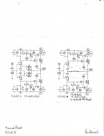
Fortunately, this Mimick maybe as simple as a power buffer from a modified F5 and/or its descendants. A representative schematic is attached [jpg and identical pdf]. Note the following.
Fortunately, this Mimick maybe as simple as a power buffer from a modified F5 and/or its descendants. A representative schematic is attached [jpg and identical pdf]. Note the following.
- The left part of the view is the parent schematic of F5 Amplifier by FW.
- The right schematic is the Mimick. The loop feedback resistors R5, R6, R7 and R8 were not used.
- The opposed drains of the complementary MOSFETs [Q3 and Q4] connect directly to the center point of the source resistors R1 and R2 of Q1 and Q2. This is the Power Output port.
- Be concerned with a possible oscillation with this [or any] power amp of unity gain.
- That's it.
Attachments
Well, this is essentially a untiy-gain CFP F5 that I happened to have discussed with Nelson about 6~12 months ago.
It simulates OK, i.e. stable with reactive load.
But I do not think it can be compared to a Complementary Source Follower as the Beast is.
Above all different gain structure and distortion spectrum.
Patrick
It simulates OK, i.e. stable with reactive load.
But I do not think it can be compared to a Complementary Source Follower as the Beast is.
Above all different gain structure and distortion spectrum.
Patrick
Well, this is essentially a untiy-gain CFP F5 that I happened to have discussed with Nelson about 6~12 months ago.
It simulates OK, i.e. stable with reactive load.
But I do not think it can be compared to a Complementary Source Follower as the Beast is.
Above all different gain structure and distortion spectrum.
Patrick
I am glad you have addressed this with Mr. Pass. I am not alone in this audio DIY universe who thinks about these matters. This unity gain CFP F5 arrangement of components reminds me of the STASIS [R,TM] power output stage. A Classic and everlasting winner.
Best regards.
Some people swear by CFPs, because it is fast.
Some people don't like them, for the same reason.
I tend to think F5 already have a lot of gain.
So perhaps it will sound a bit too "bright" in unity gain.
But there is only one way to find out ....
So don't let me discourage you.
Patrick
Some people don't like them, for the same reason.
I tend to think F5 already have a lot of gain.
So perhaps it will sound a bit too "bright" in unity gain.
But there is only one way to find out ....
So don't let me discourage you.
Patrick
Thank you for your replies. More details from you will be welcome. I visited your xen.com site, and looked at your schematics. Will a similarly configured BA3 Front End be a useful V/I converter? While I am at this idea, will a similarly configured F5 amplifer and/or descendants be useful as potent current source amps?Some people swear by CFPs, because it is fast.
Some people don't like them, for the same reason.
I tend to think F5 already have a lot of gain.
So perhaps it will sound a bit too "bright" in unity gain.
But there is only one way to find out ....
So don't let me discourage you.
Patrick
I have no front end design for such a unity gain power buffer right now.
You should perhaps ask Nelson.
Your schematics for the buffer is essentially the same as what we simulated.
There are models around for all the devices, so you can build a Spice model easy enough.
But in the end you still have to build.
Then you can come back to tell us.
Patrick
You should perhaps ask Nelson.
Your schematics for the buffer is essentially the same as what we simulated.
There are models around for all the devices, so you can build a Spice model easy enough.
But in the end you still have to build.
Then you can come back to tell us.
Patrick
- Status
- This old topic is closed. If you want to reopen this topic, contact a moderator using the "Report Post" button.
- Home
- Amplifiers
- Pass Labs
- Article: Beast With a Thousand Jfets