Dear Pro's
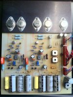
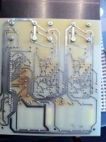
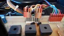
What causes the brown (heat) coloring on the PCB's of the powersupply's of this beautifull preamp?
I'm biased so I won't suggest my amature opinion..
Thanks.
What causes the brown (heat) coloring on the PCB's of the powersupply's of this beautifull preamp?
I'm biased so I won't suggest my amature opinion..
Thanks.
Attachments
It's Heat.

Wrong it's molten caramel for to induce the mellow sound of Rowland equipment.
You should try it out on your brainchilds..
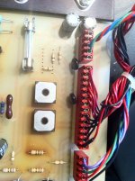
I suggest to increase distance between parts and board and substitute coloured resistors with those of higher wattage.
Of course this will cause some solder and mechanical work
I already installed six new higher wattage (2 Watts) resistors at some greater distance and ordered two Microsemi VJ247m bridges with a metal topsurface that can be heatsinked for the plus/minus 20 volts rails (the other bridge is only used for the 12 Volts necessary for operating the relays in the main unit) in my series II.
But I'm curious what causes this (surplus) heat in your opinion. Not in the sense that the components radiate heat and that decolours the epoxy layer on the fiberglass, but why do they generate so much heat.
At the first 1 Ohm resistor that's directly connected to one of the bridges I measured more then 55 degrees Celcius. The second one which is much further away but also connected to the other bridge stays just under the 50 degrees.
It's not a quiz but a real interest why these parts radiate so much heat. i suppose Jeff Rowland did not intend or forsee this behaviour/decoloring when he designed thos powersupply.
check out also this thread:
http://www.diyaudio.com/forums/soli...e-1-schematic-modules-wanted.html#post3717794
here I have an interesting question.
http://www.diyaudio.com/forums/soli...e-1-schematic-modules-wanted.html#post3717794
here I have an interesting question.
Last edited:
The main reason for heating of the resistors between rectifier and first capacitor is a much more higher value for the AC current as through the other 1R resistors behind the first capacitor (saw-tooth 100Hz).Let's rephrase the question.
What's causing the brown heatstains on the PCB of the powersupply and how can I avoid the generating heat in the future?
The schematic, which I have create, you will find here:
http://www.diyaudio.com/forums/soli...and-coherence-1-schematic-modules-wanted.html
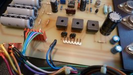
I use 4 pcs 3R9 (3W) or 10 pcs 10R (1W) in parallel mode.
Additional it is important to remove the connectors from transformer and to the male connector (mounted on rear panel). The reason therefore you will find by the last image of
http://www.audiocircle.com/index.php?topic=93368.0
The solder solution provides higher reliability.
In the last step I replace the bridge rectifiers through single diodes with fast recovery time (RGP30G):
http://www.vishay.com/docs/88704/rgp30a.pdf
This step provides a strong audible enhancement in sonic performance, particularly in such cases, where the mains is contaminated with any high frequency stuff.
P.S.: I am looking for phono modules (I+II) for opening to find out the internal circuit topology (I prefer faulty ones therefore)
Last edited:
any news?The main reason for heating of the resistors between rectifier and first capacitor is a much more higher value for the AC current as through the other 1R resistors behind the first capacitor (saw-tooth 100Hz).
The schematic, which I have create, you will find here:
http://www.diyaudio.com/forums/soli...and-coherence-1-schematic-modules-wanted.html
I use 4 pcs 3R9 (3W) or 10 pcs 10R (1W) in parallel mode.
Additional it is important to remove the connectors from transformer and to the male connector (mounted on rear panel). The reason therefore you will find by the last image of
Used Rowland M1 amp: should I worry about reliability?
The solder solution provides higher reliability.
In the last step I replace the bridge rectifiers through single diodes with fast recovery time (RGP30G):
http://www.vishay.com/docs/88704/rgp30a.pdf
This step provides a strong audible enhancement in sonic performance, particularly in such cases, where the mains is contaminated with any high frequency stuff.
P.S.: I am looking for phono modules (I+II) for opening to find out the internal circuit topology (I prefer faulty ones therefore)
I have heard, that there are at least two different power supplies for the model "Coherence ONE". What are the main differences ?
from
Used Rowland M1 amp: should I worry about reliability?
I save the last image here:
Attachments
Last edited:
I have a question to an old device with very high supply voltage - go to post #114 under
Jeff Rowland Coherence 1 - Schematic for the Modules wanted
Jeff Rowland Coherence 1 - Schematic for the Modules wanted
- Status
- This old topic is closed. If you want to reopen this topic, contact a moderator using the "Report Post" button.
- Home
- Amplifiers
- Pass Labs
- JRDG Coherence One Series I & II powersupply