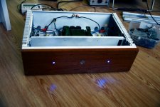
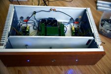
My second AB 100 ( ok AB 60 ) already singing..I made fast measurements:
95W @ 4 ohm (depends on actual mains voltage) ; 56W @ 8 ohms.
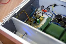
Bias -100mA per transistor. Noise level with shorted inputs -0.04mV and 0,3mV with open input.
DC offset - 9mV on both channels (i matched input ZTX with mulltimeter)
Wiring have yet to be sorted out - I still waiting missing panel mount LEDs...
accidentally running 100Khz at full output- wonder why there is no clipping but 2H distortion at MAX input.. then I realized my mistake - the heatsink was hot and the transformer started to sing - but the amplifier survived @4 ohm.
Sounds like previous amp - bass is descent!
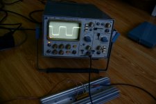
20Khz square wave picture attached.
MY amp differences from original:
input cap - 3.3 UF poly
Feedback cap 100 uf muse bipolar
capacitor instead of 68pf - 47pf mica (because I had them)
RE - 0,235R
bias generator - BD139 and 5K bias pot
95W @ 4 ohm (depends on actual mains voltage) ; 56W @ 8 ohms.
Bias -100mA per transistor. Noise level with shorted inputs -0.04mV and 0,3mV with open input.
DC offset - 9mV on both channels (i matched input ZTX with mulltimeter)
Wiring have yet to be sorted out - I still waiting missing panel mount LEDs...
accidentally running 100Khz at full output- wonder why there is no clipping but 2H distortion at MAX input.. then I realized my mistake - the heatsink was hot and the transformer started to sing - but the amplifier survived @4 ohm.
Sounds like previous amp - bass is descent!
20Khz square wave picture attached.
MY amp differences from original:
input cap - 3.3 UF poly
Feedback cap 100 uf muse bipolar
capacitor instead of 68pf - 47pf mica (because I had them)
RE - 0,235R
bias generator - BD139 and 5K bias pot
Attachments
Very interesting amp.
I have a few questions.
How do you mount PCB from Nelson's gerbers file to DIYAudio chassis?
Can I use this zenner diode instead 1N4739 ?: BZX85B9V1-TR Vishay Semiconductors | Mouser
I have a few questions.
How do you mount PCB from Nelson's gerbers file to DIYAudio chassis?
Can I use this zenner diode instead 1N4739 ?: BZX85B9V1-TR Vishay Semiconductors | Mouser
And one more question.
C1,C2 (V+) and C3,C4 (V-) = 10000uF in sum for each polarity or each cap should be 10000uF?
I start to plan BOM.")
I used four of each 10000uF caps per channel.
How do you mount PCB from Nelson's gerbers file to DIYAudio chassis?
I’ve been wondering that as well. I’m guessing one screw and standoff in the middle of the caps and then the many TIP’s basically hold the other half of the board in place. Sound about right NP?
I used four of each 10000uF caps per channel.
Thank you!
Then I guess I will start to seach something about 10000uF ~50VDC.
Lead Spacing 10mm with up to ~27mm max diameter cap.
There was idea to use Mundorf MLGO63-10000 but they are 30mm and four of them will not fit.
Maybe 2 of them (C2,C4) + 2 of smaller (C1,C3) for interesting cap "flavor".
I’ve been wondering that as well. I’m guessing one screw and standoff in the middle of the caps and then the many TIP’s basically hold the other half of the board in place. Sound about right NP?
I thought about that too.
TIP's + screw in the middle of the 10000uF caps.
No other ideas.
Thank you!
Then I guess I will start to seach something about 10000uF ~50VDC.
Lead Spacing 10mm with up to ~27mm max diameter cap.
There was idea to use Mundorf MLGO63-10000 but they are 30mm and four of them will not fit.
Maybe 2 of them (C2,C4) + 2 of smaller (C1,C3) for interesting cap "flavor".
I thought about that too.
TIP's + screw in the middle of the 10000uF caps.
No other ideas.
Here's what i used:
UKW1H103MRD Nichicon | Mouser
Here's what i used:
UKW1H103MRD Nichicon | Mouser
So it's 12.5 lead spacinng. Not that you can't bend legs a bit.
I see that Radial-Leaded caps with 10mm LS with 50VDC and higher are 6800uF max.
May be we should use 10mm LS Snap-In caps like this:
380LX103M050J052 Cornell Dubilier - CDE | Mouser
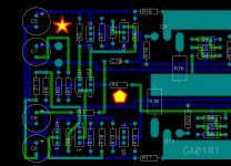
There are a couple blank regions on the board, where it has no top copper, no bottom copper, and no component bodies. Two of them are marked in yellow, below.
You could drill a hole through the board, in one or both of these locations, creating places where attachment bolts can be affixed. If you're clever about the diameter and clearance of these holes, you probably can use standard metal (electrically conductive) bolts and nuts and washers, without shorting the heatsink to any copper traces on the PCB.
But if that frightens you, switch to nylon (electrically insulating) bolts and nuts and washers. McMaster Carr sells them at typical McMC prices. With nylon fasteners you have much greater freedom to put the holes closer to copper traces, with zero danger of short circuits. So a nylon user can probably drill many more than two extra holes.
_
Attachments
50vdc caps seems a bit dangerous for me...original design have 50v rails for 100w @ 8ohm- ok on first post measurment graphs we see about 120w output...imho max 45v rails are ok with 50vdc caps.
I'm using 42V rails, so it should be OK for 50V caps.
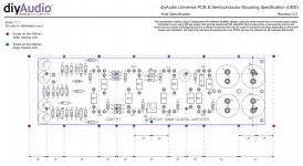
Experiment in MS paint shows Mr. Pass PCB can be mount on UMS heatsink only by solder mounted TO-247 transistors to PCB. 
I mean without drilling extra holes in heatsink or pcb.
Edit:
I will add that I am not 100% sure my sizings on attached picture are correct.
Online gerber viewer measure between TIP's center leg holes shows distance about 48mm.
And for UMS it should be 40mm. So not sure PCB are for UMS..
https://www.diyaudio.com/forums/attachment.php?attachmentid=770790&stc=1&d=1564170650
Attachments
Last edited:
There are a couple blank regions on the board, where it has no top copper, no bottom copper, and no component bodies. Two of them are marked in yellow, below.
That's what I did. Drilled in the area marked in a star at the top left. It seemed there was a bit more room there.
Snap-In mounting, 10mm lead spacing, 25mm diameter, 52mm tall, 50V rating
380LX103M050J052 — Octopart
380LX103M050J052 — Octopart
I am afraid you can't fit four 30mm diameter caps on Mr. Pass PCB.
Last edited:
I am afraid you can't fit four 30mm diameter caps on Mr. Pass PCB.
Good catch, thanks!
- Home
- Amplifiers
- Pass Labs
- AB100 Class AB Power Amplifier