I am preparing the first option for to3 - taking into account the dimensions of enclosure and transistor mounting places.
This still have to be checked - but that is the idea, and there is room for improvement (Unfortunately Iam not pro in pcb design)
base stoppers may be better to solder directly on base pins .
Trust me darlingtons will not like hardwired cables from a board to a heatsink one way or another this style of constructing originates from the 70's Twist cables between B-C-E and expect a very explosive result ( at some point the current that flows to C and E will modulate B cable with catastrophic results )
By the way ...where is your Vbe multiplier installed ? would you like to have the NVA experience ?

Last edited:
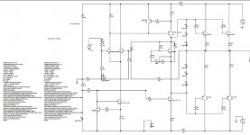
AB100 Amplifier - Micro Article by Nelson Pass
Gain: 36 dB (this was the request of the people who commissioned
this but did not want to pay for it)
Odd, this amplifier was manufactured by two separate companies for
a number of years, and I didn't hear any complaints.
I quoted post #1 regarding the history of the amplifier and it seems that in one post somebody didn't want to pay for the design and in another post it seems that the amplifier is sold and operative ....
May be its my English but i am missing something here ....
So if you like to have my statistics about darlington failure Nelson i will publish them for you
We all know the problems with darlingtons. But i think an amp designer has a much wider perspective than repair technicians.
Stability is one thing, sound quality is another. An amplifier with certain level of stability will be very safe with certain people but surely not with others.
I dont use zobels. I dont use output coils. I dont use speaker protectors. I use minimal to no compensation capacitors. In the AB100 schema you can see the miller cap with zero Farad. You can put 100pf there if you want but i think thats not the point.
I will agree with that ...in the commercial audio of class AB where all amplifiers are alike or on the same basis if you like the juice is hidden in the balance between safety and performance .
In diy though we have seen way too simple things featuring none or less of these safety features but be sure these amplifiers are not idiot proof .
I am Ok with zobel , i am ok with Coil , i am also ok with RF filter in the input which eventually will make one amplifier possible to operate in a clinical room
Here though we talk about oscillation danger just forget the rest of teh safety features .
PS
Well known amplifier top seller in Europe features miller compensation in VAS stage of 4pf power it up and works like a charm stable and sounds pretty good also ...If mains become lower than 180V amplifier becomes unstable and self destructs.
Now how often do you expect that kind of voltage drop in a European town...Statistics say that we have 3-4 of these amplifiers per year .... 4pf becomes 47 at the service and amplifier may work even if the mains is at half stable while we noticed no noticeable difference in performance or had any complain from a client .
Kind regards
Sakis
I'm probably spending more time looking at this design than I really need to , as I have amps coming out of my ears (mostly my misbegotten designs), and don't necessarily need yet one more.
I am somewhat intrigued, though, as I haven't designed an all-bipolar power amp since ~1986. This design could be updated for parts that are readily available at the usual suspects (one-stop shopping from Mouser). I had in mind the KSA1220 and KSC2690 for the VAS stages and Vbe multiplier. They are in isolated TO-126 packages, making it really easy to couple the Vbe multiplier to the main heat sink. One could go buck wild and use these parts everywhere in the front stages, especially if you get the high-beta range of the part. An alternative for the input stage might be the KSA992 and KSC1845. All these parts are readily available, and dirt cheap.
Let the TIPs stay in the output stage.
Looking at the input stage, there's a fair amount of current in the tail, and I suspect that adding some degeneration in the emitters of the input pair would be helpful. Food for thought...
I quoted post #1 regarding the history of the amplifier and it seems that in one post somebody didn't want to pay for the design and in another post it seems that the amplifier is sold and operative ....
May be its my English but i am missing something here ....
You are missing something, but the details would be embarrassing to
some parties and are best left in the "no good deed goes unpunished" file,
which contains other stories about people you think you know...

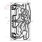
Corrected PCB :
I plan to use bipolar capacitor for feedback cap + bypass cap. Gain reduced to 26 db approx. and 0.47R for emitter resistors. Input cap will be 2,2 uf. I will use the signal ground and power ground separating resistor to prevent hum. So far I have had good experience with to-3 and short wires to pcb.
I plan to use bipolar capacitor for feedback cap + bypass cap. Gain reduced to 26 db approx. and 0.47R for emitter resistors. Input cap will be 2,2 uf. I will use the signal ground and power ground separating resistor to prevent hum. So far I have had good experience with to-3 and short wires to pcb.
Attachments
Last edited:
You are missing something, but the details would be embarrassing to
some parties and are best left in the "no good deed goes unpunished" file,
which contains other stories about people you think you know...
Fair enough i expect that some industrial secret is hidden behind this, and that is ok with me ...Eventually we all have to accept that .
Still there is too many questions placed about this and none of them is answered .
We all know the problems with darlingtons. But i think an amp designer has a much wider perspective than repair technicians.
Stability is one thing, sound quality is another. An amplifier with certain level of stability will be very safe with certain people but surely not with others.
I dont use zobels. I dont use output coils. I dont use speaker protectors. I use minimal to no compensation capacitors. In the AB100 schema you can see the miller cap with zero Farad. You can put 100pf there if you want but i think thats not the point.
I wonder why things we know as standard practice are under question in this thread ? WHY ? I am starting to get upset .
---Rf input capacitor will prevent non audible signals above 100-200KHZ to enter the amplifier
---Zobel will filter/load the output if the output is operating for any reason to a very high frequency
--- Coil will prevent any RF/AM signals to enter the amplifier from the output
Any amplifier will work without them .... perfectly i think Expect it to be sensitive to any of the above situations .
Adding is insurance for the amplifier.
Placing 100pf miller compensation is not a question of choice or question of extra safety or insurance .
More specifically 560-680pf B to C in the output stage of the known darlingtons is a speed brake of the OPS and the problem was that without them the output stage will self destruct Nothing to do with precaution/safety/insurance.
That in the past is been done for 2 transistor in the OPS imagine how things will be with 8
I'm probably spending more time looking at this design than I really need to , as I have amps coming out of my ears (mostly my misbegotten designs), and don't necessarily need yet one more.
I am somewhat intrigued, though, as I haven't designed an all-bipolar power amp since ~1986. This design could be updated for parts that are readily available at the usual suspects (one-stop shopping from Mouser). I had in mind the KSA1220 and KSC2690 for the VAS stages and Vbe multiplier. They are in isolated TO-126 packages, making it really easy to couple the Vbe multiplier to the main heat sink. One could go buck wild and use these parts everywhere in the front stages, especially if you get the high-beta range of the part. An alternative for the input stage might be the KSA992 and KSC1845. All these parts are readily available, and dirt cheap.
Let the TIPs stay in the output stage.
Looking at the input stage, there's a fair amount of current in the tail, and I suspect that adding some degeneration in the emitters of the input pair would be helpful. Food for thought...
Start messing with it and it will never be a Pass Design
There was never a question or a consideration about the input stage I have actually never been looking at it ...Imagine only yesterday i noticed that there is no RF filtering
All considerations is about the multi vibrator output stage running free and nothing else
Corrected PCB :
I plan to use bipolar capacitor for feedback cap + bypass cap. Gain reduced to 26 db approx. and 0.47R for emitter resistors. Input cap will be 2,2 uf. I will use the signal ground and power ground separating resistor to prevent hum. So far I have had good experience with to-3 and short wires to pcb.
A class AB amplifier with bias of about 80ma in a static condition will produce a small amount of heat .
If the drivers are located on the PCB regardless if those need a heatsink or not at static condition there is going to be some current flowing through them they will get some heat and stabilize .
If the amplifier is playing current that flows through the outputs will warm them up and bias will increase . Dramatically i could say when we talk about 100W amplifier and 50V rails
There you have a transistor that is usually located/bolted on the main heat sink observing temperature and its job is to reduce the bias in order to prevent thermal run away of the amplifier .
If this transistor is not located/bolted on the heatsink any amplifier in class AB even with a huge heat sink, If palying or pushed will eventually come up to thermal run away and self destruct.
Farther more having an amplifier operating if possible in a standard temperature and a standard bias will guarantee a good sound performance .
Otherwise any amplifier will play different when Cold/warm/very warm since bias will be very different according to temperature resulting a variety of distortion and a variety of harmonics content .
Now in an amplifier that operates with Darlington transistors the driver is installed inside the transistor that means that you have one temperature produced by the bias in a static condition but in play modes where the output will be warm that means that the output transistor will warm up the driver also and bias will increase 10 times faster and far more dramatically.
That means that bolting a Vbe multiplier in the heat sink suddenly is 100 times more critical than in any other circuit .
That is also why modern darlingtons SAP models have already installed inside the parts needed to compensate temperature/bias and still failed ....
Look around you .... Did you ever wonder why all applications of these transistors feature ballast resistors of 0R68 and above ?
Ideally no class AB amplifier should have ballast resistors Their job is to equalize difference between transistors ...Ideally all transistors should have equal characteristics all transistors should have equal temperature coefficient and so on and on ...
This is never going to happen in real life and that is why we use ballast resistors Even if transistors could be closely matched and/or perfect then the implementation is not perfect and that will create problems .
In Darlingtons though with a beta often of 2000 means that the gain of the device is astronomical and that will produce far more difference than a discrete output stage that is why you need more than the 0.22-0.47 standard ballast resistor Elektor BDW 83-84 used 1R10W for example and all others i know had a minimum of 0.68.
--Wire the outputs from board to heatsink
--Fail to place a proper Vbe multiplier on the heatsink
--Mess with the ballast resistors
and you have a ticking bomb in your hands ...
Please notice that the above applies to an amplifier with 2 transistors in the output ...I don't even dare to think what will happen with 8.
I wonder why things we know as standard practice are under question in this thread ? WHY ?
We both know that stability and sound quality are both important and there is often trade off between them. So the important knowledge and skill is how to make an amp stable and safe without sacrificing sound quality.
An amp with compensation caps doesnt have to be more stable than an amp without compensation caps. And we can easily make an amp bullet proof if sound quality is not important.
Input RF is important because it gives a lot to the safety but takes almost nothing from sound quality. Miller is otoh very useful and harmful at the same time. But there are unknown ways to make an amp stable without sacrificing sound.
Zobel, if only for my own use, especially if it is my design, is not required. It compromises sound quality but adds nothing to the safety
I agree with almost everything ...
Bottom line is that if miller compensation is placed carefully selected after a good study and lay in the very thin line to secure the amp without effecting the sound quality if possible then yes i Agree .
But i am not talking about that neither standard practice ( so far ) does ...560-680pf exist on the outputs because output stage wasn't safe without them .
Reminds me of thread where posters asked about oscillation problems on a circuit and got answers if zobel was installed in the output This is also clearly wrong .
560-680pf exist on the outputs because output stage wasn't safe without
I have never used such cap with my amps. May be im just lucky? Thermal runaway is the hardest part. Its easier going with no standing current at all.
I have never used such cap with my amps. May be im just lucky? Thermal runaway is the hardest part. Its easier going with no standing current at all.
I will not question your designs but i can come up wit 10 examples of what other people did while some of them might be huge manufacturers like Philips with cousins BDV66-67.
I have never used such cap with my amps. May be im just lucky? Thermal runaway is the hardest part. Its easier going with no standing current at all.
Got a question about your designs though
Do you bias them soft or hard ? Is it something like 20-50ma or is it something with 300 ma ?
I have never used such cap with my amps. May be im just lucky? Thermal runaway is the hardest part. Its easier going with no standing current at all.
Isn't this class B operation ?
Is there anyone today willing to listen in Class B ???
Hehe if looking for best sound why use darlington. But with low bias (obviously high distortion) it can sound good too.
You can't be serious about that ...
- Home
- Amplifiers
- Pass Labs
- AB100 Class AB Power Amplifier