Ok, great. I forgot about that one. So "ABFAB" for Class AB? I don't want to assume it is AB.
ABFAB is Amalgamated Brothers of Fearless Amplifier Builders
You can bias it from class AB to class A, that is entirely up to you.
Since you already have the parts you may as well have fun and build it.
I still think the Sony Vfet Part 2 amp with Lateral Mosfets will make a better Class AB amp, but we can build that later

Last edited:
DOGC-H
Hi,
I recommend you DOGC-H amplifier by Dr. Borivoje Jagodic. It uses current-dumping topology. It is class AC and sounds very good! (better than class AB amps). If you want PCB, PM me and I will send you PCB in Eagle format.
Hi Guys,
I want to build a Class AB power amp for a friend that's turning 70 this year.
Maybe should build a 70w amp to be symbolic.
A class A amp might be too much for her in terms of weight and heat.
Was thinking about the ACA, but then would need high efficiency speakers.
Might be hard for me to build/find high efficiency speakers in a small package.
I did read that the AB100 runs cool, which is a step in the right direction.
Then I could get her whatever speakers fit her style and sound.
She loves classical, operas, orchestras, etc. So, I think some power is needed.
I consider her an audiophile, because I don't know too many women who record
classical broadcasts to a digital tape recorder, although I'm sure they're out there.
I want to make something for her that sounds really good.
I'm also curious as how this amp would sound for me, so...
Does anyone have PDF or Gerber board files for the AB100?
Thanks,
Vince
Hi,
I recommend you DOGC-H amplifier by Dr. Borivoje Jagodic. It uses current-dumping topology. It is class AC and sounds very good! (better than class AB amps). If you want PCB, PM me and I will send you PCB in Eagle format.
Attachments
kacernator,
Thanks, but I already have many of the parts for a lateral Mosfet F5. Just need a transformer, case and power supply.
I have two of these unused cases and have spare heatsinks for a smaller amp.
It's a 4U chassis.
Thanks,
Vince
Thanks, but I already have many of the parts for a lateral Mosfet F5. Just need a transformer, case and power supply.
I have two of these unused cases and have spare heatsinks for a smaller amp.
It's a 4U chassis.
Thanks,
Vince
Attachments
hello guys,
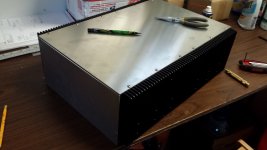
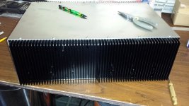
I have completed quite suitable enclosure (see attached pic) with +_42 V transformer for AB100 but but the heatsinks are to-3 pre-drilled (four to eight on each side) therefore I am seeking to-3 Darlington pairs.
I have found MJ11033/MJ11032 but they are quite expensive (approx 10EUR pcs -they are powerful - could be ok with a pair on each rail).
Maybe you have any other suggestions? Maybe BDX67B / 66B ?
tnx
Attachments
Last edited:
you would probably do better by separating the integrated Darlington into a discrete driver + output.hello guys,
I have completed quite suitable enclosure (see attached pic) with +_42 V transformer for AB100 but but the heatsinks are to-3 pre-drilled (four to eight on each side) therefore I am seeking to-3 Darlington pairs.
I have found MJ11033/MJ11032 but they are quite expensive (approx 10EUR pcs -they are powerful - could be ok with a pair on each rail).
Maybe you have any other suggestions? Maybe BDX67B / 66B ?
tnx
Try using mje15034/5 drivers and mj15003/4 or mj21193/4 or mjl21193/4outputs.
That is pretty smart Andrew and simplifies things in a way .
Question is who is going to be the one to decide the rest of the parts required and the required values on a schematic drawn by someone else .
I think that poor choice of outdated parts is what made this amp never to see the light of construction by members ....
Question is who is going to be the one to decide the rest of the parts required and the required values on a schematic drawn by someone else .
I think that poor choice of outdated parts is what made this amp never to see the light of construction by members ....
Thank you for your comments,
Yesterday I played a bit with ltspice – MJ11015/16 works fine, so I ordered them. I started diy of this amp just for fun and I like the story of the angry villagers with forks and torches and I don’t care about outdated parts or old design. According to the results of Ltspice – bias about 70mA will work fine for me – to a couple of watts it gives the smallest number of harmonics but of course I will measure it when amp will be completed.
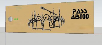
I hope that the master not being angry that I use his font for AB100 letters and I will print/burn those villagers on wood front panel.
Yesterday I played a bit with ltspice – MJ11015/16 works fine, so I ordered them. I started diy of this amp just for fun and I like the story of the angry villagers with forks and torches and I don’t care about outdated parts or old design. According to the results of Ltspice – bias about 70mA will work fine for me – to a couple of watts it gives the smallest number of harmonics but of course I will measure it when amp will be completed.
I hope that the master not being angry that I use his font for AB100 letters and I will print/burn those villagers on wood front panel.
Attachments
i Like the words you are using ....Truly people like that angry villagers with forks and torches usually in small villages i think called UK that still make some amplifiers with transistors ft 4MHZ exactly as they used to do in the 70's.
everything is a question of proper targeting and choice....
everything is a question of proper targeting and choice....
Beyond jokes now there is some things that i would like to know if you ever manage to construct ...
A few facts
From statistics point of view there is no commercial amplifier that uses more than one pair of darlingtons in the OPS (at least that i am aware off ) I expect that is done for the known stability issues .
I have seen once a car stereo amplifier that uses 4 per ch. but with 0.68 ballast resistors
In any of the available circuits that operate with any of these darlingtons there is miller caps in the region of 680pf to keep the amplifier stable, B to C for every transistor . I wonder if and how is possible to operate 8 of them without any miller compensation at all, with the twist that base stopper is at 220 R unusually big for the things that we have seen in the past .
The only known example is the NP's A40 with 4 outputs but highly biassed
I also don't recall ( but i might be wrong about this ) for the far more advanced cousins SAP15 ( which was expected having the stability/thermals problems solved and failed ...also ) and above family if there is circuits that feature more than one pair in the output ...even if ..i expect a second pair but nothing like 8 outputs per CH
Finally i expect one to simulate and fail cause even if you have a proper model for any of those the transistors will be identical in the simulation and their beta/thermal behavior will be equal and perfect , one thing that will never happen in real life ....
Yet again i wonder how fast this amplifier will be with 1R ballast resistors ....and 3-4 MHZ ft
Yet again I wonder what is the total capacitance of the OPS and if those drivers are able to to handle it ...
Valery where are you ?
Kind regards
Sakis
Last edited:
Hi Sakis and all - thank you for invitation
OK, as I normally deal with rather fast (high slew rate and wide bandwidth) front-ends, output devices with fT = 3-4MHz sound rather dangerous to me.
As usual - they close much slower than they open, being exposed to the danger of rail-to-rail cross-conductance shoot-through at fast front or high-frequency wave at the input (I had that experience some time ago, before I realized the front-end I used was just too good for those 21193/94).
You're right - to mitigate that risk, one would have to compensate heavily, limiting the bandwidth and slowing down the voltage amplification stages.
But isn't it easier to use some modern RET devices with fT = 30-50MHz?
I like those villagers
Cheers,
Valery
OK, as I normally deal with rather fast (high slew rate and wide bandwidth) front-ends, output devices with fT = 3-4MHz sound rather dangerous to me.
As usual - they close much slower than they open, being exposed to the danger of rail-to-rail cross-conductance shoot-through at fast front or high-frequency wave at the input (I had that experience some time ago, before I realized the front-end I used was just too good for those 21193/94
).You're right - to mitigate that risk, one would have to compensate heavily, limiting the bandwidth and slowing down the voltage amplification stages.
But isn't it easier to use some modern RET devices with fT = 30-50MHz?
I like those villagers
Cheers,
Valery
Thanks for join in Valery my questions about this remain here for the past years .
There is one think more that i asked and never got an answer
I constructed A40 with Tip 142 -147 with anything available parts without a mosfet for a current source wasn't available and replaced it with a just a resistor
Biased it if i remember well at 800ma and there it was rock solid stable without miller caps .
My conclusion was that if the Darlington is biased hard doesn't oscillate .
Can you comment that ?
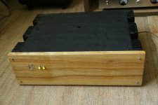
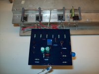
Here is the pic of the A40
made 5-7 years ago a sloppy job with anything available parts but still solid rock
There is one think more that i asked and never got an answer
I constructed A40 with Tip 142 -147 with anything available parts without a mosfet for a current source wasn't available and replaced it with a just a resistor
Biased it if i remember well at 800ma and there it was rock solid stable without miller caps .
My conclusion was that if the Darlington is biased hard doesn't oscillate .
Can you comment that ?
Here is the pic of the A40
made 5-7 years ago a sloppy job with anything available parts but still solid rock
Attachments
What, 4 MHz not fast enough for audio?
When the average Japanese manufacturer used 30Mhz in the 70's then i expect for high quality audio NO its not enough ...
But who am I to argue that in front of you ?
I am just a statistics keeper Nelson ....
From statistics point of view there is no commercial amplifier that uses more than one pair of darlingtons in the OPS (at least that i am aware off ) I expect that is done for the known stability issues .
My conclusion was that if the Darlington is biased hard doesn't oscillate .
I have an amp using 3 pairs of darlington per channel (2N6284/87 Motorola, one of the best sounding darlington, TO-3). It is lowly biased looking from the size of the heat sink, which is basically using its casing of 100% Aluminium.
I forget the brand as everything (amp labelling) are in german Incl the parts such as dual jfet from vishay.
Thanks for join in Valery my questions about this remain here for the past years .
There is one think more that i asked and never got an answer
I constructed A40 with Tip 142 -147 with anything available parts without a mosfet for a current source wasn't available and replaced it with a just a resistor
Biased it if i remember well at 800ma and there it was rock solid stable without miller caps .
My conclusion was that if the Darlington is biased hard doesn't oscillate .
Can you comment that ?
Here is the pic of the A40
made 5-7 years ago a sloppy job with anything available parts but still solid rock
I can't say anything particular on this one, at least before I see the feedback loop gain/phase response curves. Have you got the exact schematic of that build?
- Home
- Amplifiers
- Pass Labs
- AB100 Class AB Power Amplifier