Hi all,
I recently built a clone of F5 (stock, rev. 1, dual mono, 250VA transformers/8x15mF/23.7V per channel).
It's still has a few hours of burning in time, but sounds (sounded ) well.
Not yet much experience in electronics ("can read with a dictionary"), hence some dummy questions:
currently I am trying to measure its square wave response, and it does not look very impressive (miles away from the nice green 200kHz pic in the manual on the firstwatt site): one channel has very much rounded corners, the other has a significant overshoot on top half and some undershoot on the bottom half (sorry, no pictures yet - will try to take them whenever I can). This is the same for different frequencies - 10k, 50k, 100k. The input signal amplitude is 1Vpp from a Tek AFG3102 signal gen, and it looks good when fed directly into the scope (Tek TDS320).
I tried it without a load and with 6ohm speakers connected (don't have a proper resistor for load), I have tried to rotate transformer, move input wires a bit - no change.
What can be wrong here - bad layout/wiring/resistors matching?
What amplitude of the test signal is safe to feed into F5? My understanding was it's about +-2.5V max, is that correct?
Yesterday I tried to test it with an innocent 2.5kHz square wave (again, 1Vpp), this gave me bad oscillation on the overshooted/undershooted channel, I even noticed HF noise coming from the amp (no speakers connected), then something started to smoke (very slightly), and I noticed the signal amplitude on the scope started to compress a bit, and I immediately shut it off. Switched it on later without any input, no smoke, but did not check yet if it's alive or not. Could not identify visually if anything has been burnt - no colour change or anything else.
Really appreciate any advise from more experienced of you than me
PS I did search quite a lot prior to post here, but still did not find or recognize the answers
I recently built a clone of F5 (stock, rev. 1, dual mono, 250VA transformers/8x15mF/23.7V per channel).
It's still has a few hours of burning in time, but sounds (sounded
) well.Not yet much experience in electronics ("can read with a dictionary"), hence some dummy questions:
currently I am trying to measure its square wave response, and it does not look very impressive (miles away from the nice green 200kHz pic in the manual on the firstwatt site): one channel has very much rounded corners, the other has a significant overshoot on top half and some undershoot on the bottom half (sorry, no pictures yet - will try to take them whenever I can). This is the same for different frequencies - 10k, 50k, 100k. The input signal amplitude is 1Vpp from a Tek AFG3102 signal gen, and it looks good when fed directly into the scope (Tek TDS320).
I tried it without a load and with 6ohm speakers connected (don't have a proper resistor for load), I have tried to rotate transformer, move input wires a bit - no change.
What can be wrong here - bad layout/wiring/resistors matching?
What amplitude of the test signal is safe to feed into F5? My understanding was it's about +-2.5V max, is that correct?
Yesterday I tried to test it with an innocent 2.5kHz square wave (again, 1Vpp), this gave me bad oscillation on the overshooted/undershooted channel, I even noticed HF noise coming from the amp (no speakers connected), then something started to smoke (very slightly), and I noticed the signal amplitude on the scope started to compress a bit, and I immediately shut it off. Switched it on later without any input, no smoke, but did not check yet if it's alive or not. Could not identify visually if anything has been burnt - no colour change or anything else.
Really appreciate any advise from more experienced of you than me
PS I did search quite a lot prior to post here, but still did not find or recognize the answers
Last edited:
check output offset.
check output bias.
connect to your source (wave generator) with generator output turned down to ZERO.
check output offset.
check output bias.
Turn up the 1kHz (or close) signal to 10mVac.
Measure the F5 output waveform. use both a DMM set to 2.000Vac and use your scope to measure the peak to peak. Expect about 180mVpp for 60mVac.
Add a standard 22r across the output. The power will be ~ 0.14mW
Add a second 22r for an 11r loading.
Add a third 22r for a 7r3 loading.
Slowing turn up the gen signal from 10mVac to 100mVac. Power in each resistor will rise to 16mW. They will still be cold.
switch to different frequencies and check the wave shape stays same or similar.
check output bias.
connect to your source (wave generator) with generator output turned down to ZERO.
check output offset.
check output bias.
Turn up the 1kHz (or close) signal to 10mVac.
Measure the F5 output waveform. use both a DMM set to 2.000Vac and use your scope to measure the peak to peak. Expect about 180mVpp for 60mVac.
Add a standard 22r across the output. The power will be ~ 0.14mW
Add a second 22r for an 11r loading.
Add a third 22r for a 7r3 loading.
Slowing turn up the gen signal from 10mVac to 100mVac. Power in each resistor will rise to 16mW. They will still be cold.
switch to different frequencies and check the wave shape stays same or similar.
a standard 1/4W or 1/2W resistor.
I happen to have 600mW because we have them here in Europe and they are cheap.
Some amplifiers do not like operating without some load.
Amplifiers that have no Thiele Network, nor output Zobel have no load. These may particularly require a little bit of loading.
Oops, that word should be slowly !
I happen to have 600mW because we have them here in Europe and they are cheap.
Some amplifiers do not like operating without some load.
Amplifiers that have no Thiele Network, nor output Zobel have no load. These may particularly require a little bit of loading.
Oops, that word should be slowly !
Thanks Andrew,
here is quite a bit to try for me.
So far:
offset (while setting the bias, not while testing with sig gen) is ~ +-5mV
bias ~1.3A (~880mV across r68)
"Some amplifiers do not like operating without some load"
- having a 6 Ohm speaker is not considered as a load?
will get and post those with sq. wave in later
Best,
Alex.
Last edited:
Well, commonly signal generators assume a 50 Ohms load and for that load they're calibrated.
So, unless your signal generator is a different type, you need a 50 Ohm resistor (higher wattage type for serious signal) in parallel to the amp input; also I recommend koaxial 50 Ohms wiring from the generator to the input.
Hannes
So, unless your signal generator is a different type, you need a 50 Ohm resistor (higher wattage type for serious signal) in parallel to the amp input; also I recommend koaxial 50 Ohms wiring from the generator to the input.
Hannes
Indeed they have good current capability.
Both my generators are 50ohm. That requires an internal 50r in the feed to the output BNC, then 50ohm coax to the load and finally 50r load across the coax output.
I think mine have a 5Vac max output (into 50r). But that is still only 1/4W into the 100r load that the output stage sees.
Both my generators are 50ohm. That requires an internal 50r in the feed to the output BNC, then 50ohm coax to the load and finally 50r load across the coax output.
I think mine have a 5Vac max output (into 50r). But that is still only 1/4W into the 100r load that the output stage sees.
Last edited:
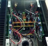
Sorry was busy at work, so could not get the pics earlier. The good news is the amp is still alive and sound good (at least to my unspoiled taste). With some good speakers was hard to believe that there is no subwoofer involved.
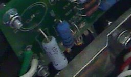
The pictures were taken by web camera hence the quality...
Here is the overview and the source resistor proximity to the FET (which is buried under the thick aluminium bracket)
The pictures were taken by web camera hence the quality...
Here is the overview and the source resistor proximity to the FET (which is buried under the thick aluminium bracket)
Attachments
Well, commonly signal generators assume a 50 Ohms load and for that load they're calibrated.
So, unless your signal generator is a different type, you need a 50 Ohm resistor (higher wattage type for serious signal) in parallel to the amp input; also I recommend koaxial 50 Ohms wiring from the generator to the input.
Hannes
- yes, mine says 50 Ohm at its output too, but I don't have such cable, only 75 Ohm. Would 50/75 Ohm impedance matching adaptor help?
You cannot test an amp using a speaker as a load. I thought I was having problems as well until someone told me that
OK, that explains some of my results then. I don't have 22Ohm resistors as Andrew T. advised, so have to wait to make 'proper' tests.
I think I also need a 'proper' (50 Ohm) coaxial cable to connect signal generator to the amp.
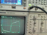
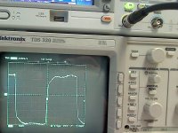
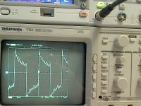
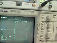
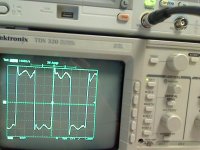
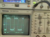
Nonetheless, here are some of my current measurements - taken at 10k, 50k, 100k and 200k for both channels. Whatever distortion is contributed by wrong cables/load/etc there is still quite a discrepancy between the channels.
It obviously also degrades badly at higher frequency.
I am going to take it apart to check how this asymmetry may depend on transformers location.
The first row (first 5 images) is for the left channel. Note on the 5th image (probs_swap...) the signal was affected if I did swap the probe's polarity (i.e. connecting probe gnd to the amp hot rather than to the amp gnd). I tried to push/rotate the rca connector - no change. When I swap probe (gnd to the amp gnd gnd, hot to the amp hot), it looks better (pic. 1).
This prob swapping effect is only seen on the left channel.
Thanks,
Alex.
Attachments
-
 R_200.jpg583.5 KB · Views: 50
 -
 R_100.jpg568.3 KB · Views: 59
 -
 R_50.jpg586 KB · Views: 61
 -
 R_10.jpg556.3 KB · Views: 66
 -
 probs_swap_only_seen_on_the_left.jpg642.5 KB · Views: 61
 -
 L_200khz.jpg515.1 KB · Views: 71
 -
 L_100khz.jpg594.7 KB · Views: 323
 -
 L_50khz.jpg558.8 KB · Views: 333
 -
 L_10khz.jpg574.4 KB · Views: 380
Last edited:
Add a standard 22r across the output. The power will be ~ 0.14mW
Hi Andrew,
0.14mW or 0.14W (or 14mW)?
How is it calculated?
Thanks,
Alex.
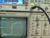
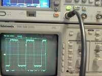
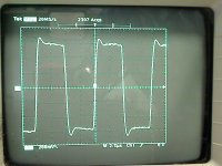
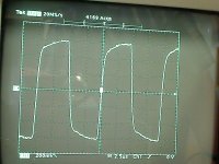
Here are some results with 3x22R [parallel] resistors, as Andrew advised.
The signal in is square 100mVpp (not sure is it same as 100mVac?) at 100kHz.
Looks a bit cleaner at this amplitude, but the general picture is the same - overshoot on the left and h. freq loss on the right.
Any idea what may cause this? (should not be layout, as I ripped of the heatsinks with PCBs, moved them away from the amp and tested each channel individually - same results. The only thing I missed to try - swap the PSUs, and my right ch. trans has some buzz - is it possible it affects the signal in the way described?)
Attachments
- Status
- This old topic is closed. If you want to reopen this topic, contact a moderator using the "Report Post" button.
- Home
- Amplifiers
- Pass Labs
- F5 measurement/tuning