You might as well use the single diode bridge with the Brian GT psu board - I used it in a F5 project, with the same diodes you linked, it worked well. Remember to get big heatsinks for the diodes, however.
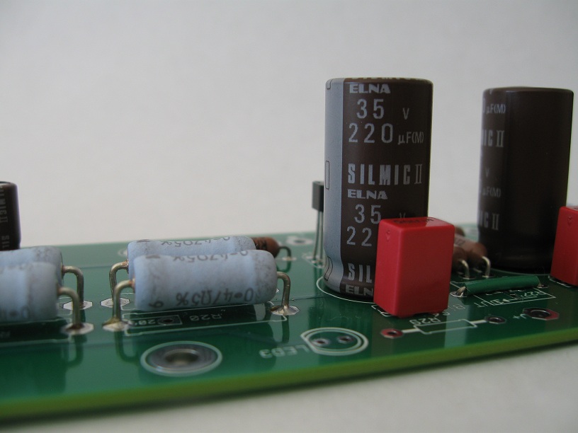
I used (6) 33,000uf caps on that board, I really like it. I have another assembly just like it, which will likely be used on my Aleph J.
I used (6) 33,000uf caps on that board, I really like it. I have another assembly just like it, which will likely be used on my Aleph J.
You might as well use the single diode bridge with the Brian GT psu board - I used it in a F5 project, with the same diodes you linked, it worked well. Remember to get big heatsinks for the diodes, however.
I used (6) 33,000uf caps on that board, I really like it. I have another assembly just like it, which will likely be used on my Aleph J.
Got my caps today from Digi-Key. 6 Panasonic THA 33000uF 35V caps. I originally ordered 12, but DK wanted to charge me 60$ shipping for my order even though it was over $200. The other parts were some 3W resistors and pots. I then changed my order to 6 caps to get free shipping. So now I must order the other 6 with some other order. What made me furious was that when the box was delivered this morning by FedEx, the parts (caps and other) was only like 5% the contents of the box, and the box must have weighed heavier than the contents. The other 6 caps could easily have fitted in there and the weight would not have changed by much.
Sometimes it just sucks living down here in never-neverland.
I like the $4.99 Mouser Economy shipping in US. Gas to the nearest electronic store is more for me. Usually if I place an order on Sunday, I have by Friday.
What I like about this Aleph J project is that I can swap in the amp board quickly with my F5. I would like to do the F5T someday, but the cost of 5U chassis is close to $500. That could be better spent else where in my system - speakers, DAC, cartridge, preamp - more vinyl. 6L6 - I hope you got the 'bro' deal from the DIYAudio store for doing the build guide!
What I like about this Aleph J project is that I can swap in the amp board quickly with my F5. I would like to do the F5T someday, but the cost of 5U chassis is close to $500. That could be better spent else where in my system - speakers, DAC, cartridge, preamp - more vinyl. 6L6 - I hope you got the 'bro' deal from the DIYAudio store for doing the build guide!
Got my caps today from Digi-Key. 6 Panasonic THA 33000uF 35V caps. I originally ordered 12, but DK wanted to charge me 60$ shipping for my order even though it was over $200. The other parts were some 3W resistors and pots. I then changed my order to 6 caps to get free shipping. So now I must order the other 6 with some other order. What made me furious was that when the box was delivered this morning by FedEx, the parts (caps and other) was only like 5% the contents of the box, and the box must have weighed heavier than the contents. The other 6 caps could easily have fitted in there and the weight would not have changed by much.
Sometimes it just sucks living down here in never-neverland.
Next time send me a pm. Ill order the stuff n ship it to you.
Got to be cheaper.
I don't mind as long as I have the $ in my play fund. You can paypal me back when u get da stuff.
Next time send me a pm. Ill order the stuff n ship it to you.
Got to be cheaper.
I don't mind as long as I have the $ in my play fund. You can paypal me back when u get da stuff.
Thanks for the offer. I will keep it in mind for next time.
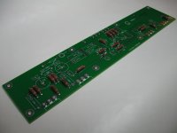
Here is a progress report on the prototype boards 6L6 sent me.
For this initial build I decided to use the schematic Nelson Pass posted here:
http://www.diyaudio.com/forums/pass-labs/111197-aleph-j-schematic.html#post1341101
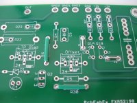
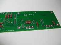
So I installed jumpers on the positions of the optional components.
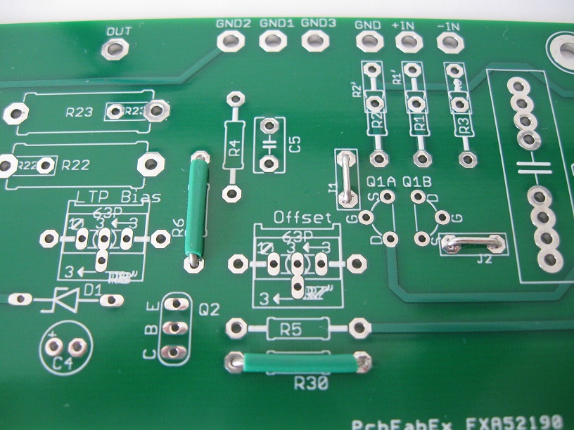

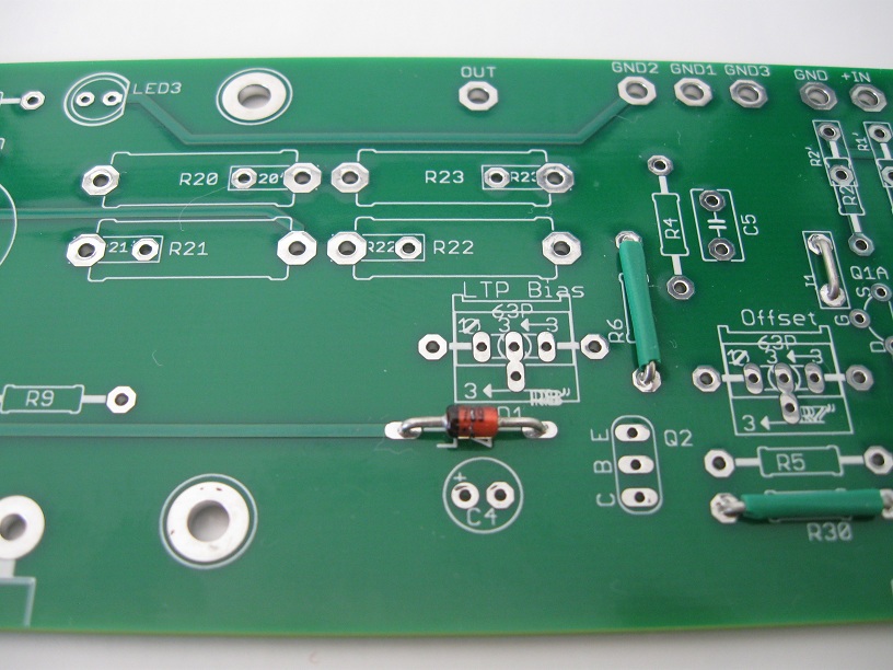
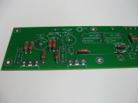
Next I installed the Zener...
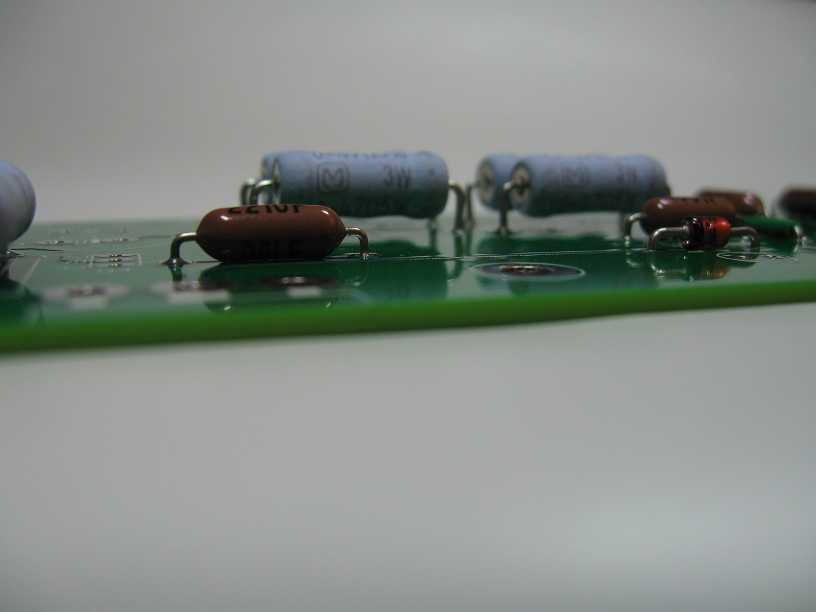
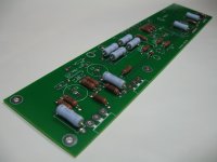
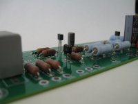
... and the regular resistors. I used Vishay/Dale RN60 and CMF60.
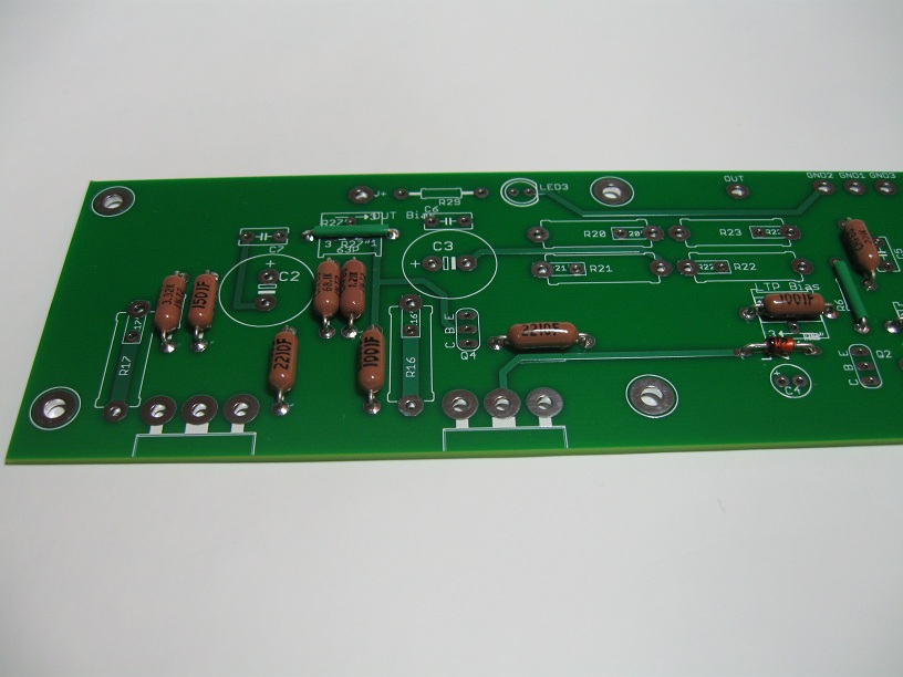

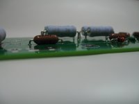
I then installed the power resistors, leaving a gap at the bottom so they don't touch the PCB.

For this initial build I decided to use the schematic Nelson Pass posted here:
http://www.diyaudio.com/forums/pass-labs/111197-aleph-j-schematic.html#post1341101
So I installed jumpers on the positions of the optional components.
Next I installed the Zener...
... and the regular resistors. I used Vishay/Dale RN60 and CMF60.
I then installed the power resistors, leaving a gap at the bottom so they don't touch the PCB.
Attachments
-
 Jumpers.JPG189.8 KB · Views: 1,276
 -
 Panasonics3.JPG75.5 KB · Views: 1,227
 -
 Panasonics2.JPG73.6 KB · Views: 1,241
 -
 Panasonics1.JPG110.3 KB · Views: 1,295
 -
 Dales3.JPG108.9 KB · Views: 1,227
 -
 Dales2.JPG112.5 KB · Views: 1,261
 -
 Dales1.JPG109.9 KB · Views: 1,221
 -
 Zener.JPG159.5 KB · Views: 1,273
 -
 JumperR27.JPG173 KB · Views: 1,230
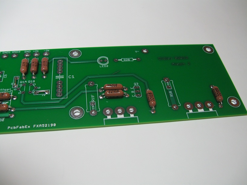
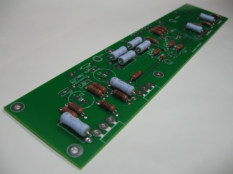
After all resistors were installed, I soldered the capacitors and the Zetex devices (ZTX450 and ZTX550)
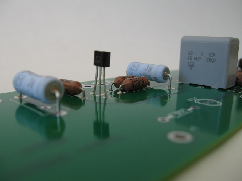

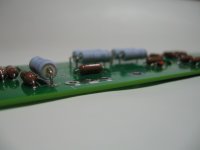
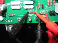
Soldered the JFETs, mounted on the heat sink and started it.
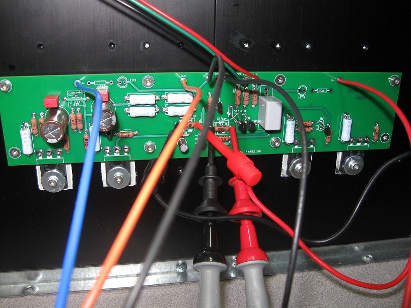

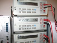
The rails were set to +23V/-23V using a Variac and two handheld meters not shown in the picture. The top meter shows measurement across R8, the one in the middle across R7 and the bottom meter shows the DC offset at the output.

Soldered the JFETs, mounted on the heat sink and started it.
The rails were set to +23V/-23V using a Variac and two handheld meters not shown in the picture. The top meter shows measurement across R8, the one in the middle across R7 and the bottom meter shows the DC offset at the output.
Attachments


") Very nice job!
Very nice job!About the board
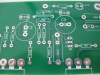
The holes for the Zener need to be increased. Fairchild devices will not fit, Vishay ones did fit but were very tight. I worked on them using 220 grit sandpaper and polished them with 00 steel wool.
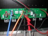
Another issue was the edge of the board where the MOSFETs are mounted. It projects over the body of the devices and, in my case, using 5mm tall standoffs the PCB was touching them. I worked around that raising the standoffs with washers. Looking at the picture showing the board mounted on the heat sink, it is easy to tell that the distance from the mounting holes to the edge of the board is shorter at the top than it is at the bottom. I think we can safely trim that bottom edge, making the board the same exact dimensions as the F4 PCB and, at the same time, resolving the problem described above.
The holes for the Zener need to be increased. Fairchild devices will not fit, Vishay ones did fit but were very tight. I worked on them using 220 grit sandpaper and polished them with 00 steel wool.
Another issue was the edge of the board where the MOSFETs are mounted. It projects over the body of the devices and, in my case, using 5mm tall standoffs the PCB was touching them. I worked around that raising the standoffs with washers. Looking at the picture showing the board mounted on the heat sink, it is easy to tell that the distance from the mounting holes to the edge of the board is shorter at the top than it is at the bottom. I think we can safely trim that bottom edge, making the board the same exact dimensions as the F4 PCB and, at the same time, resolving the problem described above.
About my build
I managed to assemble both boards but was only able to start one of them. Because of unexpected delays on Sunday it was late in the evening when I finally fired up the first channel. At 1 KHz the square wave looks great, at 500 Hz top and bottom are slanted and, at 10 KHz, the sides are sloped. Feeding directly from a CD player the sound was clean however, using the same player on the F5 it played much, much louder. I did connect the Aleph J's negative input to ground.
In the coming days I will perform additional measurements and post images and values. I wanted to complete the build to confirm that the PCB works and report the issues I found.
Those of you who have already built an Aleph J may be able to give me some feedback on the measurements posted so far.
- Home
- Amplifiers
- Pass Labs
- Aleph J for Universal Mounting Spec