Do not quite understand what she said!.
A scheme would be excellent. thank you
I don't have a pot on the input like yours but here is sort of what I did.
Attachments
....................
Just for curiosity , does your preamp has zero resistance between grounds of both RCA?
hello,
Yes, all the pre RCAs have common mass.
I'll be too perfectionist? Is it normal to hear this hum F5 to 20cm column?
I've tried everything, used a bridge rectifier on earth, and everything stays the same.
In place of listening I do not hear the hum, but I fear that change the sound to get louder.
After the experiences I made some improvements and got the standard connections, and the little hum!!
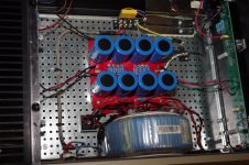
When I bought the capacitors 15000UF came a pack of 10, only have 8 at the source, I wonder if it would have any benefit in putting these 2 that are on the shelf.
It could connect them at the entrance of PSU in parallel with R of 2.2 K! I had already asked this question but no answer. Thanks guys
I've tried everything, used a bridge rectifier on earth, and everything stays the same.
An externally hosted image should be here but it was not working when we last tested it.
In place of listening I do not hear the hum, but I fear that change the sound to get louder.
After the experiences I made some improvements and got the standard connections, and the little hum!!
An externally hosted image should be here but it was not working when we last tested it.
An externally hosted image should be here but it was not working when we last tested it.
When I bought the capacitors 15000UF came a pack of 10, only have 8 at the source, I wonder if it would have any benefit in putting these 2 that are on the shelf.
It could connect them at the entrance of PSU in parallel with R of 2.2 K! I had already asked this question but no answer. Thanks guys
Blink,
where are your pics?
the images are at the beginning
http://www.diyaudio.com/forums/pass-labs/224531-f5-normal-ics-twist-out-hum.html
I can't see any pics.
Not in post1, nor in the link you so kindly provided.
Did you remember to attach them?
Other members can see the images because they respond to questions.
They housed the Imageshack, you can not see the pics of ImageShack?
I'll put on my website for you, and say now you see ...
An externally hosted image should be here but it was not working when we last tested it.
An externally hosted image should be here but it was not working when we last tested it.
An externally hosted image should be here but it was not working when we last tested it.
An externally hosted image should be here but it was not working when we last tested it.
An externally hosted image should be here but it was not working when we last tested it.
An externally hosted image should be here but it was not working when we last tested it.
An externally hosted image should be here but it was not working when we last tested it.
An externally hosted image should be here but it was not working when we last tested it.
An externally hosted image should be here but it was not working when we last tested it.
An externally hosted image should be here but it was not working when we last tested it.
Now it is so.
An externally hosted image should be here but it was not working when we last tested it.
An externally hosted image should be here but it was not working when we last tested it.
Hi,
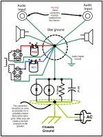
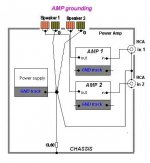
Attached it is ground schematic that I used when everything failed. Always worked. Before try it connect the chassis ground as close as possible to the PS ground. The distance sometime make a different.
The GND of the right and left pcbs (R1 and R2) and R10 do not connect the GND PSU?
The negative speaker does not turn to the central point of the capacitors (0 Volts)?
The large currents flowing through the columns should not return to the center point of the capacitors?
I have had problems with similar PCB. After trying everything like you, I changed the caps from 15000 uF to 22000 uF and everything become quite. My 2 cents.
The hum disappeared?
reduced or eliminated hum, due to replacing bad capacitors, or bad soldering.
Not to do with the change from 15mF to 22mF.
What is effect of PS ripple over the output? Isn't less ripple less hum?
Blink,
Please attach your pics.
You have no idea how much these remotely located pics slow down the page load, due to automatic download of the full pic file/s. Compared to attached pics, which download the thumbnail and leave the big pic download as an option.
Hello,
Now put by another process, hope you see the images.
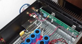
If you disconnect the Interconnects do not hear any hum, connecting ICs appears a little hum, so many experiences that I've done I can only doubt is that the defect PCBs.
The grounds were all disconnected cables IECm but does not change anything!
greetings
Attachments
Hi Blink_PT
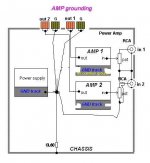
Let's do some debugging of your grounding arrangement.")
All I will say is referring to the pics in your last post.
1- The wire from the loudspeaker return, the black output terminal, must be connected to the 0 of the power supply, near the electrolytic capacitors.
2- The ground terminal of both RCA input connectors must be connected together via a wire ( not too thin, and if possible, solid core).
3- The middle point of this wire must be connected to the 0 volts power supply reference, joining the loudspeaker return wire ( see 1). Once again use a not too thin wire.
4- From the input boards to the RCAs, take out the coaxial and use a not too thin wire between boards and the RCA grounds. Obviously you must do it in both channels. Later if you prefer you can use a coax, but with screen connected just at one end, that way it will carry no signal.
Good grounding practices keeps hum away...
That's all folks.
Let's do some debugging of your grounding arrangement.
All I will say is referring to the pics in your last post.
1- The wire from the loudspeaker return, the black output terminal, must be connected to the 0 of the power supply, near the electrolytic capacitors.
2- The ground terminal of both RCA input connectors must be connected together via a wire ( not too thin, and if possible, solid core).
3- The middle point of this wire must be connected to the 0 volts power supply reference, joining the loudspeaker return wire ( see 1). Once again use a not too thin wire.
4- From the input boards to the RCAs, take out the coaxial and use a not too thin wire between boards and the RCA grounds. Obviously you must do it in both channels. Later if you prefer you can use a coax, but with screen connected just at one end, that way it will carry no signal.
Good grounding practices keeps hum away...
That's all folks.
Hi Blink_PT
Let's do some debugging of your grounding arrangement.
All I will say is referring to the pics in your last post.
1- The wire from the loudspeaker return, the black output terminal, must be connected to the 0 of the power supply, near the electrolytic capacitors.
2- The ground terminal of both RCA input connectors must be connected together via a wire ( not too thin, and if possible, solid core).
3- The middle point of this wire must be connected to the 0 volts power supply reference, joining the loudspeaker return wire ( see 1). Once again use a not too thin wire.
4- From the input boards to the RCAs, take out the coaxial and use a not too thin wire between boards and the RCA grounds. Obviously you must do it in both channels. Later if you prefer you can use a coax, but with screen connected just at one end, that way it will carry no signal.
Good grounding practices keeps hum away...
That's all folks.
Hello,
Thanks Jorge for your help, but I have some questions to confirm.
I made a little diagram of what you said, and I look like this:
The Amp GND of right and left (R1 and R2) and R10 will not connect GND PSU?
The big currents working in loudspeakers should not return to the center point of the capacitors?
Blink
Attachments
- Status
- This old topic is closed. If you want to reopen this topic, contact a moderator using the "Report Post" button.
- Home
- Amplifiers
- Pass Labs
- F5 - is normal ICs twist out the Hum?