Hello Everyone : I just purchased a set of the Cascoded F5 pcb's. Please advise me as to how to construct this amplifier ! Any help would be greatly appreciated !
Where did you get them from? That's where you should start. If from the DIY store, check Civler's blog explaining them.
Russellc
I was trying to be too clever: All else falls into place once the HS are selected, because to choose a HS, one must first have decided power output, number of output devices, and bias point, which combined decide the PS size. Also, the HS sets most of the cost and influences the construction type (appearance).
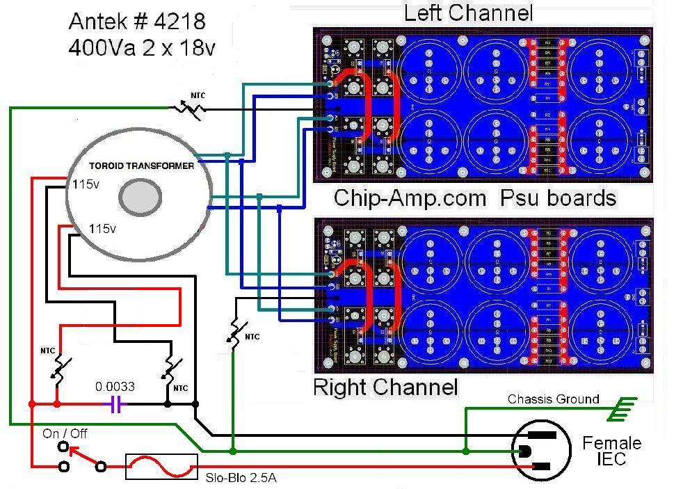
Using 18VAC secondaries takes the "need" to cascode away. You can just use a few jumpers on the PCB and not use the cascode hardware. The original F5 was built with 18VAC secondaries without cacodes. However, for more output power you probably want higher voltage secondaries and a cascoded input.
There is also the possibility that cascoding could give better sound? There is no reason you can't use the cascode with your 18VAC secvondaries.
There is also the possibility that cascoding could give better sound? There is no reason you can't use the cascode with your 18VAC secvondaries.
......what can be expected from using a lower voltage ?
maybe less demands on heatsinks, and safer for driving 4ohm speaker
but if you plan to drive more inefficient speakers......

.... tell me what you think
that you should try and learn to wire them yourself
after that you are free to buy it 'readymade'

Dantimax.com boards
at Mikkel's prices can afford to use two boards per channel
though Im not a fan of those screw teminals
and 10A may be a bit on the low side
Attachments
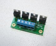
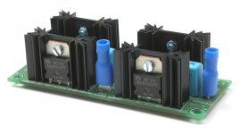
Tinitus, I have the universal power supply board, it has several things I don't really care fore 1) rectifier section, 2) power-supply caps if using 8 are 30mm diameter and 3) the screw mounting holes are to close to the caps so now a 25mm almost becomes your max diameter. Ideally I would like to see something like the "Chipamps.com" Aleph psu boards but with 8 caps @ 40mm..... This is what I'll probably end up doing >
Last edited:
- Status
- This old topic is closed. If you want to reopen this topic, contact a moderator using the "Report Post" button.
- Home
- Amplifiers
- Pass Labs
- Cascoded F5