I've been thinking along similar lines. I am curious why you left the 750R source resistors but tied the sources together.
Seems like that would give too much gain for a BOSOZ, but should work for an XBOSOZ. Are the 750R's there to reduce dissipation in the CCS?
Why trim both of the drain resistors? I could see it if you were planning to DC couple a cascode to get a DC coupled output, but don't understand it when capacitively coupled.
I have no formal EE training past EE101, just trying to understand this stuff.
Variations on a theme by Pass
Goody, goody gumdrops...it worked.
You'd think that they'd let you know that there's an 800x1200 pixel limit on images prior to trying to attach a file. Oh, well. It's resized. It's here. Time to move on.
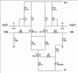
There's been some interest in the past in a BOSOZ (aka Bride Of Son Of Zen, aka Balanced Zen Line Stage) with a current source instead of the set of 750 ohm resistors underneath. Okay, fair enough. There was also a post recently by a member who wanted a BOSOZ-ish circuit to use as a phase splitter. Okay. Then I went and posted the Follower of Zen output stage in the SOZ w/current sources thread. Naturally, being a follower, it needs a bit of gain ahead of it to help it get off the ground. The natural candidate would be the BOSOZ, which is really just a differential...which would also function very nicely as a phase splitter if only it had a current source underneath it.
I'm only going to gloss over the circuit at the moment as I'm short on time. Going from top to bottom:
--"Hey, whazzup with the load resistors, bub? Weren't the original fixed 750 ohm 3W resistors good enough?" Sure they were, but the member who wanted a phase splitter specified a 'precision' phase splitter. Now, I've never had any problem getting excellent matching out of the two phases of output from a differential used as a phase splitter, but if you want to go down to multiple decimal points of accuracy, you might want to be able to match things a little more finely. Hence, the resistor triplet for each gain MOSFET's load. They provide a few percent adjustment up and down. Don't need them? Great! Put in one 750 ohm 3W (the blue Panasonic ones from Digikey will work just fine) on each side and go. If you can't visualize it, go to www.passdiy.com and look up the original paper Nelson wrote on the "Balanced Zen Line Stage."
--"Where's all the Zeners an' stuff?" View this circuit as a building block, not a finished preamp. If you want a preamp, tag in whatever you want/need from the original paper. If you want to use it as the first stage of an amplifer, you'll have different requirements. For instance, I put 100k resistors on the Gates of the output devices in the "Follower of Zen." These will serve quite nicely to discharge the 10uF caps at the output of this circuit if you should want to mate the two. If you want to use it as a stand-alone circuit, putting resistors at the outputs would be a good idea. Again, see Nelson's paper.
--"I thought you said this thing had a current source. Why'd you put in R5 an R8?" To decrease the power dissipation in the current source MOSFET. I've got a cascode current source drawn up. If there's sufficient interest, I'll post that one, too. For the time being, I was trying to stay within shouting distance of Nelson's original circuit.
--"What's that junk at the bottom of the schematic? That wasn't in Nelson's circuit!" That's the current source. Current sources are an emotional topic for some people. Everybody has a favorite design. This one is a circuit that Nelson has used many times in his commercial gear and I thought it would be more in the spirit of the thing if I were to use something he might use.
--The caveat is that I haven't built this circuit. Yet. I did the math late the other night, reviewed it once I'd gotten an hour or two of sleep, and I think it'll probably fly. Since then I've been fighting a recalcitrant upload system here trying to get it posted.
--I said it once, I said it twice, I said it thrice, and I'm gonna say it again: Read Nelson's original paper before tinkering with this circuit. It's not difficult to understand, but it'll be easier still if you understand its family history.
I'll try to post more later if I can find some time.
Grey
P.S.: If you catch me in a math error or something of that nature, say it gently. I bite when I'm this short on sleep.
Goody, goody gumdrops...it worked.
You'd think that they'd let you know that there's an 800x1200 pixel limit on images prior to trying to attach a file. Oh, well. It's resized. It's here. Time to move on.
There's been some interest in the past in a BOSOZ (aka Bride Of Son Of Zen, aka Balanced Zen Line Stage) with a current source instead of the set of 750 ohm resistors underneath. Okay, fair enough. There was also a post recently by a member who wanted a BOSOZ-ish circuit to use as a phase splitter. Okay. Then I went and posted the Follower of Zen output stage in the SOZ w/current sources thread. Naturally, being a follower, it needs a bit of gain ahead of it to help it get off the ground. The natural candidate would be the BOSOZ, which is really just a differential...which would also function very nicely as a phase splitter if only it had a current source underneath it.
I'm only going to gloss over the circuit at the moment as I'm short on time. Going from top to bottom:
--"Hey, whazzup with the load resistors, bub? Weren't the original fixed 750 ohm 3W resistors good enough?" Sure they were, but the member who wanted a phase splitter specified a 'precision' phase splitter. Now, I've never had any problem getting excellent matching out of the two phases of output from a differential used as a phase splitter, but if you want to go down to multiple decimal points of accuracy, you might want to be able to match things a little more finely. Hence, the resistor triplet for each gain MOSFET's load. They provide a few percent adjustment up and down. Don't need them? Great! Put in one 750 ohm 3W (the blue Panasonic ones from Digikey will work just fine) on each side and go. If you can't visualize it, go to www.passdiy.com and look up the original paper Nelson wrote on the "Balanced Zen Line Stage."
--"Where's all the Zeners an' stuff?" View this circuit as a building block, not a finished preamp. If you want a preamp, tag in whatever you want/need from the original paper. If you want to use it as the first stage of an amplifer, you'll have different requirements. For instance, I put 100k resistors on the Gates of the output devices in the "Follower of Zen." These will serve quite nicely to discharge the 10uF caps at the output of this circuit if you should want to mate the two. If you want to use it as a stand-alone circuit, putting resistors at the outputs would be a good idea. Again, see Nelson's paper.
--"I thought you said this thing had a current source. Why'd you put in R5 an R8?" To decrease the power dissipation in the current source MOSFET. I've got a cascode current source drawn up. If there's sufficient interest, I'll post that one, too. For the time being, I was trying to stay within shouting distance of Nelson's original circuit.
--"What's that junk at the bottom of the schematic? That wasn't in Nelson's circuit!" That's the current source. Current sources are an emotional topic for some people. Everybody has a favorite design. This one is a circuit that Nelson has used many times in his commercial gear and I thought it would be more in the spirit of the thing if I were to use something he might use.
--The caveat is that I haven't built this circuit. Yet. I did the math late the other night, reviewed it once I'd gotten an hour or two of sleep, and I think it'll probably fly. Since then I've been fighting a recalcitrant upload system here trying to get it posted.
--I said it once, I said it twice, I said it thrice, and I'm gonna say it again: Read Nelson's original paper before tinkering with this circuit. It's not difficult to understand, but it'll be easier still if you understand its family history.
I'll try to post more later if I can find some time.
Grey
P.S.: If you catch me in a math error or something of that nature, say it gently. I bite when I'm this short on sleep.
metalman,
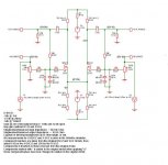
Rail voltages in the original were +-60V. I tried to set this up to work on the same rails. The circuit will work with higher or lower voltages, but some minor adjustments should be made to the current source if you stray too far from the original power supply.
Bob,
I started with the current source taking the entire voltage from the negative rail all the way up to the bottom of the differential. Power dissipation was on the order of 3.75W. This is well within the ratings for an IRF610, so if you want to remove R5 & R8, it'll work just fine. Just be sure to put a pretty decent heatsink on Q2. Since most folks use the little stamped aluminum sinks with cut fins, I opted for reduced heat. Those little heatsinks aren't good for much wattage.
Hopefully my other post answered your question about the load resistors--use the adjustable version on one side, both sides, or neither. The stock BOSOZ used 750 ohm fixed resistors, but even that's not graven in stone. Use 1k if you like, or 511, or 2.21k...whatever suits your fancy. Just make sure that they'll take the heat.
jwb,
Agreed, but see above.
Tazzy,
Actually, I'd prefer to use tabs at the beginning of paragraphs, but The Powers That Be seem to feel that whitespace characters (i.e. non-printing characters like tabs and such) are forbidden. In fact, multiple spaces are pared down to one, something that drives people crazy when they try to make simple diagrams using ASCII characters in their posts.
For those who prefer not to use Zener diodes due to noise concerns, D1 can be substituted with an 1820 ohm resistor. It will slightly raise the current through the differential, but that might even arguably improve the sonics of the circuit. The rails are regulated, so it should provide a fairly stable reference voltage for the current source MOSFET.
Grey
Grey,
Thanks for your posts! I'm building a stock BOSOZ as a test bed and want to try a couple of ps variations and a constant current source before finishing it with volume control & chassis. I don't know that much about electronics, but I've followed some of the discussions about the sound of BOSOZ with and without ccs.
I understand your approach with R5 and R8 is to limit the power dissipation in the current source MOSFET, but does that affect the performance of the ccs? I guess my real question is: would the circuit get fullest benefit from the ccs (whether it sounds better or not) by eliminating R5 & R8 and putting a big heatsink on the MOSFET?
Ren
Ren,
To the extent that the current source in this application is there to provide a lot of impedance, adding resistance on top of it helps. However, given the impedance of the current source, the mere 375 ohms of the two resistors in parallel falls into the category of guilding the lily. In short, more resistance in that position helps, not hurts--but the amount added is so small that it's kind of a wash.
On the other hand, those two resistors are going to be cheaper than an appropriate heatsink. Feel free to try both ways.
Grey
Grey,
I have arranged an identical CCS in my BOSOZ.
Q1. Can the original gain adjustment resister be included (R15) here with the isolation provided by the 750R resistors on the Source of each Fet , or are (2) independant CCS required?
Q2. Gain. Can the gain be varied by means other than R15 or padding the input with a voltage divider?
From my own research in the original article Mr Pass describes the gain of the circuit is the ratio of the impedance of the output circuit divided by the impedance of the circuit that couples Q1 & Q2 (R15).
So R1 +R2 =1.5K/ 124 (R15)+12+12 (Q1&2 apparent source resistance) = 10 (20DB).
Therefore if we keep R15 = 0 ohms, Can the value of R1 & R2 be reduced to reduce the overall gain of the circuit while maintaining the Dc bias conditions?
The reason I ask these questions is that I have used Hendrik's X modification on my BOSOZ and would like to operate the circuit in the X mode but with less apparent feedback (ie 20db).
My thinking is that the X theory would be better applied if the original circuit had lower open loop gain, and a small amount of feedback would make both sides identical. Some reading also suggests the hall of mirrors effect of large amounts of feedback when applied to high gain circuits using the X mode.
Alternatively, perhaps you have an alternative to the BOSOZ using the X mode which maybe more appropriate.
Ian
Attachments
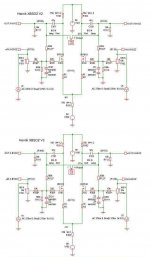
XBSOZ with about 10db feedback.
Ian
As you can see in my attached scematics, you can replace R15 (from the original scematic) with two resistors R1 and R2 in my new scematics. This way you get an T tail instead of an Pi - as in the original BSOZ scematic, which makes it simpler especially if you want to use just one current sink (CCS) as replacement for R103 in my scematic.
You can lower the gain by R101 an R102, but the you will reduce the both bandwith and max. output swing, but since both these parameters are generous, you can reduce R101 and R102 to not less than 150 Ohm and then reduce R1 and R2 to 18 Ohm. This will give you about 10db feedback with maximum X-communication between both halves of the diffpair, like in my XBSOZ V3.
I have tried some variations between my first incarnation and the variations 2 and 3, but the difference in sound is very subtle, and I still like my first XBOSOZ the best, may be love at first sight, I am not quite shure.
Regards
Attachments
Hendrik,
Thankyou for sharing your design variations and comprehensive explanation.
These are interesting possibilities, I will certainly try them.
I assume if the low ohms variable resistance was connected in V 2 & 3 at the node of both Fet sources like R15 it was act as a variable gain control.
As a matter of interest, if you operate with an X Aleph, do you capacitor couple the input to the power amp?
Ian
Ian
Quote: "As a matter of interest, if you operate with an X Aleph, do you capacitor couple the input to the power amp?"
You woun´t get any DC at the outputterminals of the XBSOZ unless you pressent some DC to the input, then you will get a fraction of this at the output besause of the feedbackresistors.
If your Aleph-X has some DC at the inputterminals, could happen, the you will get a fraction of this at the input of the XBSOZ, again because of the feedbackresistors.
This DC-behavieur is diffrent from the original BSOZ which is entierly capacitor coupled, but on the other hand, i dont think it is a problem as long as the DC levels are low, and the XBSOZ will not go up in smoke or something like that, only the biaspoints will change. Try with and without caps.
I am eager to red about your variations, I think the equipment used in the entire setup is a parameter as well.
Happy building.
Regards
The original BSOZ has also about max. 25V outputswing, but it takes 2.5V at the input to get it when the gain is 10.
But normally we only need something in the neigbourhood of 2V output, and with a gain of 10 this means 200mV at the input which is about normal.
I guess Nelson made it this way, because he wanted more flexibility for the use of the BSOZ. The relatievley high outimpedance is caused by the high value of R1 and R2 in the original scematic, lowering them will give you lower outimpedance.
If you lower R1 and R2 you also get less distortion.
The relatievley high outimpedance is caused by the high value of R1 and R2 in the original scematic, lowering them will give you lower outimpedance.
What values would you suggest? / How low value will you need to notice a change? (It is the 750 ohm resistors we are talking about?).
Arne K
- Status
- This old topic is closed. If you want to reopen this topic, contact a moderator using the "Report Post" button.
- Home
- Amplifiers
- Pass Labs
- The BOSOZ variations