If I were to build a balanced line stage using two mosfets paralleled, two 80mA current sources, and 4 750 ohm load resistors per channel, would it lower the distortion? If so, about how much of an improvement would this make? I noticed that by paralleling two zen stages together the distortion is reduced, and in the pearl phono there are 4 paralleled jfets on the input for lower distortion. Would it be of benefit to quadruple the fets and current in a BLS?
Steve
Steve
Interesting question. What difference does it make if you double the devices but double the current too?
I posed a similar question before in another thread and nobody answered. Maybe we'll get lucky this time around.
There is a plot in NP article, the graph is THD vs. Vout. The plot shows three curves for increasing PS voltages. As the PS voltage increases the output distortion decreases and the minimum of such distortion curves moves to higher values of output voltage. The question is how low can you push the distortion while increasing the PS voltage? Basically, how much low distortion gain can one squeeze out of this circuit?
From my understanding of it, the distortion goes down as the power supply voltage rises due to increased bias current through the fets. There would obviously be an upper limit to this, as the dissipation would exceed what the FET could handle, and you couldn't use a bigger FET because the increase in capacitance leads to more distortion. Maybe I'm going about this the wrong way; maybe I need to use lower power devices (maybe even JFETS) and run them in quads. I don't know that paralleling the FETS used in this circuit would help much...??? Maybe somebody could help us out here. I'm kinda puzzled by the whole thing, and I'm not sure what question to even ask, you know? How about, is the input capacitance of this circuit directly related to the distortion of the circuit?
Steve
Steve
All other things being equal, parallel MOSFETs is the
same as a bigger MOSFET except that it is already
nicely matched. The original Aleph P use IRF240's
as the gain devices, and they worked great. You
can really bias them up, say as high as 1 amp
with 25 volts across them.
same as a bigger MOSFET except that it is already
nicely matched. The original Aleph P use IRF240's
as the gain devices, and they worked great. You
can really bias them up, say as high as 1 amp
with 25 volts across them.
I've build the BLS almost the way you plan (just two mosfets, two active current sources). In the prototyping phase, I've tested the design with different bias currents, and found that IMHO the more you increase it, the better the sound. I stopped at 80 mA/Mosfet (IRF610) mainly for the global dissipation issue. I'm more than happy with the lush sound it provides, but I still wonder how it would have sound with an heavier bias ") . I think you should give it a try before paralleling.
. I think you should give it a try before paralleling.
I still haven't found a clear explanation of the "bias increase"/"sound improvement" relation - apart from distortion decrease. Any hints ?
Regarding the number of //ed JFets in phono stages, I think it first addresses the noise issue (decorrelated noise is divided by the square root of n, n being the number of fets). Am I wrong ?
Cheers,
. I think you should give it a try before paralleling.I still haven't found a clear explanation of the "bias increase"/"sound improvement" relation - apart from distortion decrease. Any hints ?
Regarding the number of //ed JFets in phono stages, I think it first addresses the noise issue (decorrelated noise is divided by the square root of n, n being the number of fets). Am I wrong ?
Cheers,
I think that is what I will do also- increase the bias current. I suppose that it lowers distortion because the fet is in a more linear range. Nelson explained in one article (can't remember which one) that this is why MOSFETs aren't good to drop into class AB circuits- they aren't linear near cutoff.
I may also try paralleling two MOSFETS to get a little better noise performance. The only thing that I worry about is the increase in gate capacitance. I wonder if that will be alright with the source?
BTW, what load resistors did you end up using with your 80mA current sources? I was running a simulation with 100mA current sources at +/-50V, and I came up with 220ohm load resistors. I changed the resistors on the power rails from 22.1 to 10, because they were dropping a lot of voltage at the higher currents.
Anyone know if it is possible to cascode this circuit?
Steve
Hi,
Don't have my schematics handy, but I think the drain resistances were 500 Ohms (Caddock MP915, TO-126 case). The positive rail is at +85V, and negative one at -40V (to reduce dissipation in current sources - MJE15030 BJT + Led)
I'm sure you can cascode the circuit. Never tried, but seems quite possible.
Cheers,
Hi,
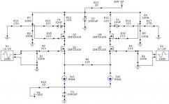
I've tried a quick simulation (see attached image). It gives good results but no sound.
Well, regarding the gate voltage for the cascode mosfets, a rough approximation gives :
Starting from the input mosfet : gate @ 0V
Allow 10-15V more on its drain. Add 4.5V for the Vgs of the second mosfet. You get about 20V at the gate. Be sure that Ibias x Rload voltage drop let sufficient room for the second mosfet to behave correctly (10-20V more positive than the gate). That's only a quick way to go, but seems to work... And maybe I'm completely wrong
Hope this helps
I've tried a quick simulation (see attached image). It gives good results but no sound
.Well, regarding the gate voltage for the cascode mosfets, a rough approximation gives :
Starting from the input mosfet : gate @ 0V
Allow 10-15V more on its drain. Add 4.5V for the Vgs of the second mosfet. You get about 20V at the gate. Be sure that Ibias x Rload voltage drop let sufficient room for the second mosfet to behave correctly (10-20V more positive than the gate). That's only a quick way to go, but seems to work... And maybe I'm completely wrong
Hope this helps
Attachments
Ok, a couple of quick observations:
Steve, I suggest you use pots of R8 and R9, and you
probably want to lower the value as Q1 and 2 probably
don't need so much voltage across them to perform
well and it cuts into your output swing. I assume
that R16 and 17 are simulation loads, and would otherwise
be removed.
Francois, I think you'll end up wanting a few hundred
ohms output resistance to isolate you a bit from the
outside world. Also, V3 and V4 can easily be the same
source.
Nelson,
Thanks for your kind observations. Of course, it's far from a practical circuit, it was only for quick simulation purposes, just to test the feasability (?) of some ideas. It's a long way from computer screen to music listening
Steve,
I don't think that noise is really an issue here. My BLS is dead quiet, provided that power supply is correctly filtered.
Nelson,
Thanks for the advice. I will try a smaller value of pot (50K?) to dial in the gate voltage. Is there a better way of biasing the cascode fets into conduction?
I'm still not exactly clear on how to determine the operating point of the mosfets... I believe that in this case it is controlled by the current source, but I'm not sure how to determine the optimal value of load resistor and current. Does the gate voltage not matter, as long as it is biased above 4-5 volts?
- Status
- This old topic is closed. If you want to reopen this topic, contact a moderator using the "Report Post" button.
- Home
- Amplifiers
- Pass Labs
- paralleling mosfets in BLS