Hello, for an amplifier project I need an amplifier for single input to drive two grids, class A, precisely push-pull. Output must be around +/- 4 V, as it is class A, no power needed. Until now have used 3 OPA 134 for amplification and phase inversion. That does not sound bad, but seems to be improvable. Now I have bought Jensen 123 slpc transformers, and I will drive them with OPA 134, so that I need only one OP and one transformer, no capacitors.
The other idea is to use a balanced Zen Line Stage or probably better, an ALEPH P 1.7, of which I know the circuit, for this purpose. That would mean capacitors again. Who knows ?
Best regards and many thanks for your interest.
oliver krug
The other idea is to use a balanced Zen Line Stage or probably better, an ALEPH P 1.7, of which I know the circuit, for this purpose. That would mean capacitors again. Who knows ?
Best regards and many thanks for your interest.
oliver krug
olvrkrg said:Hello, for an amplifier project I need an amplifier for single input to drive two grids, class A, precisely push-pull. Output must be around +/- 4 V, as it is class A, no power needed. Until now have used 3 OPA 134 for amplification and phase inversion. That does not sound bad, but seems to be improvable. Now I have bought Jensen 123 slpc transformers, and I will drive them with OPA 134, so that I need only one OP and one transformer, no capacitors.
The other idea is to use a balanced Zen Line Stage or probably better, an ALEPH P 1.7, of which I know the circuit, for this purpose. That would mean capacitors again. Who knows ?
Best regards and many thanks for your interest.
oliver krug
Hi Oliver,
I tried it - but I have one big problem with your mail: what is your question?!
Please describe in a very easy way again what you need. As far as I read between the lnes something like exactly any Pass preamp can do: convertion unbalanced to balanced. Or what?
Regards
Klaus
If I'm reading your post correctly, you want to drive a tube circuit, but you want to do it with a solid state front end.
A circuit that takes a single-ended signal as input and gives a balanced one as output is called a phase splitter. A differential (such as you find in several of Nelson's designs) with a current source underneath will give you very good balance between the phases. The same general circuit is possible with tubes. I use something like this as the first stage of my tube amps.
Grey
This thread was created by my referring Oliver here to look
for examples of current-sourced BSOZ so as to achieve
precision balanced outputs from a single input. As
as has been pointed out before, the BSOZ biased with a
resistor(s) to the negative rails does a workable but not
a precise job of creating a balanced output from a single
input. Any suggestions to him on a current source?
OK> I need an amplifier for single input to drive two grids, class A, precisely push-pull.
NP> current-sourced BSOZ so as to achieve precision balanced outputs from a single input. As as has been pointed out before, the BSOZ biased with a resistor(s) to the negative rails does a workable but not a precise job of creating a balanced output from a single input. Any suggestions to him on a current source?
With hollow-state triodes, the ideal value is not a perfect current source but more like the plate impedance. A too-high tail impedance will reduce balance precision.
With BJT, we forgot this.
For FET, I would look at using the same type FET as the diff-pair. I think that gives near-exact correction for "plate resistance" unbalances. Certainly better balanced than any two tubes ever are.
Moreover: with P-type devices, you can easily couple to negative-bias grids, without capacitors, and have a bias trim.
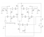
Apologies to Pass: this is not meant to be faithful to SOZ details. It will need work from someone more familiar with these devices to get it to work, work well, sound sweet.
This was sketched for some high-drive grids, and uses a JFET instead of the IGFETs seen in most of Pass's designs. None of that matters. It will actually work better (pull-up higher) with typical IGFETs than with common JFETs, and the rails could be scaled down to 12V or whatever seems right for the grids in use.
The negative supply should be more than twice as large as the grid bias. For 25V bias, -60V is a starting place for design; I suppose 9V might be a trial point for 4V grids. The positive rail should probably be the same or down to about half that: +60 to +30V for my 25V grids.
Adjusting the pot in the long-tail source sets the DC bias at the grids. A balance pot will surely be needed to get the diff-pair FETs to balance and put the same bias on both grids, or to offset the bias to "match" un-matched tubes.
Over on the right is a simulation-only rig for checking balance. As far as I can figure, the sum of the two drive signals is EXACTLY zero (plus the bias voltage), and the peak levels are equal, showing(?) perfect balance.
In a hasty run, I don't see any whacky behavior, medium-signal or even in gross clipping. With JFET, it is not possible to pull-up to Gate level (zero volts); with enhancement-mode IGFETs it should be possible since their "grids" sit on the other side of the "cathode" (my age is showing...)
NP> current-sourced BSOZ so as to achieve precision balanced outputs from a single input. As as has been pointed out before, the BSOZ biased with a resistor(s) to the negative rails does a workable but not a precise job of creating a balanced output from a single input. Any suggestions to him on a current source?
With hollow-state triodes, the ideal value is not a perfect current source but more like the plate impedance. A too-high tail impedance will reduce balance precision.
With BJT, we forgot this.
For FET, I would look at using the same type FET as the diff-pair. I think that gives near-exact correction for "plate resistance" unbalances. Certainly better balanced than any two tubes ever are.
Moreover: with P-type devices, you can easily couple to negative-bias grids, without capacitors, and have a bias trim.
Apologies to Pass: this is not meant to be faithful to SOZ details. It will need work from someone more familiar with these devices to get it to work, work well, sound sweet.
This was sketched for some high-drive grids, and uses a JFET instead of the IGFETs seen in most of Pass's designs. None of that matters. It will actually work better (pull-up higher) with typical IGFETs than with common JFETs, and the rails could be scaled down to 12V or whatever seems right for the grids in use.
An externally hosted image should be here but it was not working when we last tested it.
The negative supply should be more than twice as large as the grid bias. For 25V bias, -60V is a starting place for design; I suppose 9V might be a trial point for 4V grids. The positive rail should probably be the same or down to about half that: +60 to +30V for my 25V grids.
Adjusting the pot in the long-tail source sets the DC bias at the grids. A balance pot will surely be needed to get the diff-pair FETs to balance and put the same bias on both grids, or to offset the bias to "match" un-matched tubes.
Over on the right is a simulation-only rig for checking balance. As far as I can figure, the sum of the two drive signals is EXACTLY zero (plus the bias voltage), and the peak levels are equal, showing(?) perfect balance.
In a hasty run, I don't see any whacky behavior, medium-signal or even in gross clipping. With JFET, it is not possible to pull-up to Gate level (zero volts); with enhancement-mode IGFETs it should be possible since their "grids" sit on the other side of the "cathode" (my age is showing...)
OK, I proved I forgot how to bias a MOSFET.
I found a P-MOSFET model. However it is gigantic (some TO-3 device) so I scaled all resistances much lower than we would use in a grid-driver. Someone who has played with small modern MOSFETs will have to adjust to more realistic values. I think the performance will be similar with a MOSFET about 10 times smaller and all resistors scaled 10 times higher.
The current source will now work with enhancement-mode MOSFETs. Thermal drift may be a problem, so I used an identical MOSFET for gate bias. In my model, with fixed-voltage bias, a rise from 25°C to 50°C threw the output nodes so far that the tube would be cut-off. With this scheme, bias is pretty constant with a slight trend to reduce tube current at high operating temperature. However I have seen power MOSFETs biased Class AB with just a Zener, so maybe my model exagerates thermal drift and we don't need a matching MOSFET for bias.
The 1Meg "Rload" is just a simulation convenience, not needed in a real amplifier.
It can swing the grids above ground, even though the Gates are grounded. It clips around +3V. Output shape when swinging +0.8V to -8.8V:
Gain seems to be 10V grid-grid out from 0.07V in, or over 100. This will change when scaled to smaller devices and more reasonable impedances. If less gain is needed, larger source resistors will cut gain and distortion and improve DC balance stability.
Distortion several dB below clipping reads under 0.5% and all 3rd harmonic. This is probably low S-D voltage on the MOSFETs, and it reduces at lower levels. At 2.8V grid-to-grid, SPICE says 0.05%, for what little that is worth.
At high level, just below clipping, the two output both hit +2.1495V and 2.1497V, symmetrical to than 0.01%. When clipping, one side hits +3.7V and the other hits +3.6V, a balance error, because the source node is bopping up and down that much. On a grounded-cathode stage, this is well into grid current. This should be insignificant compared to tube mis-matching error, especially in the grid current range.
I found a P-MOSFET model. However it is gigantic (some TO-3 device) so I scaled all resistances much lower than we would use in a grid-driver. Someone who has played with small modern MOSFETs will have to adjust to more realistic values. I think the performance will be similar with a MOSFET about 10 times smaller and all resistors scaled 10 times higher.
An externally hosted image should be here but it was not working when we last tested it.
The current source will now work with enhancement-mode MOSFETs. Thermal drift may be a problem, so I used an identical MOSFET for gate bias. In my model, with fixed-voltage bias, a rise from 25°C to 50°C threw the output nodes so far that the tube would be cut-off. With this scheme, bias is pretty constant with a slight trend to reduce tube current at high operating temperature. However I have seen power MOSFETs biased Class AB with just a Zener, so maybe my model exagerates thermal drift and we don't need a matching MOSFET for bias.
The 1Meg "Rload" is just a simulation convenience, not needed in a real amplifier.
It can swing the grids above ground, even though the Gates are grounded. It clips around +3V. Output shape when swinging +0.8V to -8.8V:
An externally hosted image should be here but it was not working when we last tested it.
Gain seems to be 10V grid-grid out from 0.07V in, or over 100. This will change when scaled to smaller devices and more reasonable impedances. If less gain is needed, larger source resistors will cut gain and distortion and improve DC balance stability.
Distortion several dB below clipping reads under 0.5% and all 3rd harmonic. This is probably low S-D voltage on the MOSFETs, and it reduces at lower levels. At 2.8V grid-to-grid, SPICE says 0.05%, for what little that is worth.
At high level, just below clipping, the two output both hit +2.1495V and 2.1497V, symmetrical to than 0.01%. When clipping, one side hits +3.7V and the other hits +3.6V, a balance error, because the source node is bopping up and down that much. On a grounded-cathode stage, this is well into grid current. This should be insignificant compared to tube mis-matching error, especially in the grid current range.
Hi all.
Link to unbal to bal converting:
http://www.diyaudio.com/forums/showthread.php?s=&threadid=5558&perpage=15&highlight=&pagenumber=1
http://www.diyaudio.com/forums/showthread.php?postid=75141#post75141
What about this nice xamp which makes an presice conversion.
I have used this one for my analog output in my CDP (only slightly modified) with a grat result:
Attachments
Nelson Pass said:This thread was created by my referring Oliver here to look
for examples of current-sourced BSOZ so as to achieve
precision balanced outputs from a single input. As
as has been pointed out before, the BSOZ biased with a
resistor(s) to the negative rails does a workable but not
a precise job of creating a balanced output from a single
input. Any suggestions to him on a current source?
Is there any problem in having not 100% balanced outputs?
I have made some tests, I can´t hear the difference between 10% (bsoz and xbsoz without CCS) mismatch in amplitude and the perfect match (bsoz and xbsoz with CCS), but the CCS will in my oppinion degrade the soud only very little compared to resistors at the tail.
Take a look at the links I made in my earlier post.
Take a look at the links I made in my earlier post.
If you are using them to bridge amplifiers that otherwise wouldOriginally posted by Bricolo Is there any problem in having not 100% balanced outputs?
be single-ended inputs, the disparity in amplitude will cause some
loss of maximum power and reduced common-mode rejection,
but is otherwise not a problem.
Also look at:
http://www.metaxas.com/pages/technology/diy.html
More specifically:
http://www.metaxas.com/images/technology/diy3.gif
jonathan carr
http://www.metaxas.com/pages/technology/diy.html
More specifically:
http://www.metaxas.com/images/technology/diy3.gif
jonathan carr
- Status
- This old topic is closed. If you want to reopen this topic, contact a moderator using the "Report Post" button.
- Home
- Amplifiers
- Pass Labs
- Preamplifier balanced output, single input