Ive been thinking a lot about how to give the components of a SOZ the lowest possible running temperature.
Ive machined a round cabinet of aluminium (20mm wall thickness 180mm high 450mm diameter) and mounted the heatsinks on the outer diameter all the way around (around 35kg of heatsinks, all machined to fit).
The point of this is to be able to run all components at the same temperature by simply mounting them closer or further from the center of the box at the bottom side (exept the mosfets that will be mounted on the upper side alone to make sure they are plenty cooled).
I thought of the option to mount the components on a block of copper and then mount the copper on the aluminium, to take advantage of the excellent heat transfer properties of copper at the relatively small surface i have between the component and the copper...and then make the copper block lets say 4 times the footprint of the component and mount it in the box....
anybody knows if the loss of heat transfer between the respective surfaces is too big to make this work??
Magura
A couple of comments.
1. I am very jealous of your machining tool access.
2. Using copper as a heat spreader plate works very well. I have done this in the past while designing a 400MHz to 860MHz Class A push pull amp using a LDMOS device that had two mosfets in the same package. Bias dissapation was around 10 watts and the package just wasn't big enough to get the heat out of in our space requirements without going to a 1/4" thick copper spreader plate first.
A later version of the design did go straight to aluminum, but I had forced air cooling working for me there.
Use thermal compound (sometimes called heatsink grease) and make sure both devices are as flat as possible.
Scott
Magura said:What i really wanted to know was if it pays off...is it a good idea.
The making of such is no big deal.
Im a toolmaker in diecasting and have acces to any machine i could ask for.
Magura
ScottRHinson said:A couple of comments.
2. Using copper as a heat spreader plate works very well. I have done this in the past while designing a 400MHz to 860MHz Class A push pull amp using a LDMOS device that had two mosfets in the same package. Bias dissapation was around 10 watts and the package just wasn't big enough to get the heat out of in our space requirements without going to a 1/4" thick copper spreader plate first.
what ratio did you have between the size of footprint (resistor-copper> copper-aluminium) ?
Magura
Magura said:
what ratio did you have between the size of footprint (resistor-copper> copper-aluminium) ?
Magura
The transistor package had a total surface area of .186 sqaure inches. I kind of went overkill on the copper spreader. It was 2"x4", .5" thick. For short times of debugging it was enough of a heatsink by itself. What kind of output devices are you using, how many and how much power will they be dissipating?
Scott
Nelson Pass said:The SOZ was specifically designed to appeal to guys who
aren't afraid of big hardware but are a little shy about
circuit complexity. Interestingly this appears to comprise
a large segment of the DIY community.
.
Sure we love the Zen thing, but i guess mostly for a different reason.
A complex circuit just takes a little more time, but most of us would be able to make such.
I chose the SOZ because it stands out of the ordinary in any way possible :
It sounds great, once youve heard one of the Zen amps...youre impressed.
Its quite a challenge to make something like that, and make it look good.
They look impressive.

And last but not least, DIY people likes to be different, and they sure achieve that by having a SOZ in the living room.
Magura
Zen #6 (Flower Power)
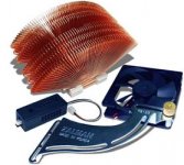
I use these heatsinks in both my computers... I got tired of all the
freakin' fan noise about a year a go.
An arrangement of these would make a pretty cool looking amp,
and you can spin the fans at a very low RMP at which they are
very quiet. It sure would let you build the amp a lot smaller! Just
dedicate 1 FET for each heatsink. They would easily dissipate
25 to 35 watts i'm sure. I suppose the only trick would be to set
up an independent power supply just for the fans.
Attachments
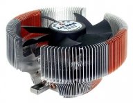
doing some research, CPU cooling solutions for computers can be much cheaper than those mushroom versions. Thermaltake for example makes a few models that can be had for about 20 bucks that can dissipate 50 watts or more with a 25 degree increase temperature. Could be a viable option depending on your needs. Certainly would be an interesting looking project
It's best to be careful with thermaltake products. A few of them have gone up in smoke, due to the method they use to control the fans rotational speed. On user selectable models they simply use a 3 pole switch with 3 .5w resistors in parallel(and the fans draw well over this rating).
Has anyone considered the HSF units that Intel supply with their Pentium 4's?
These can be picked up for around $15 AUD($8-10US) and all the plastic junk from them can be removed leaving just the fan.. or if you're daring you can use it in the mounting system
Has anyone considered the HSF units that Intel supply with their Pentium 4's?
An externally hosted image should be here but it was not working when we last tested it.
These can be picked up for around $15 AUD($8-10US) and all the plastic junk from them can be removed leaving just the fan.. or if you're daring you can use it in the mounting system
- Status
- This old topic is closed. If you want to reopen this topic, contact a moderator using the "Report Post" button.
- Home
- Amplifiers
- Pass Labs
- Heat dissipation