BTW, for those hung up on light bulbs, there was a Heathkit push-pull amplifier circuit a long time back using light bulbs for emitter ballast resistors. One of the virtues claimed was a bit of inherent current limiting. Given all the stuff on the internet these days, it might not be too hard to find that circuit and launch a separate thread for discussion.
If you want a good symmetrical amp, you should look at "Le Mutant" (do a search in the Pass forum). There's no Schade involved, it's all about modulated asymmetric current mirrors. It also sounds very nice, and has little to no output offset with no servo. This requires selecting the input diff pair rather closely, but thar's the breaks.
Thanks wrenchone.If you want a good symmetrical amp, you should look at "Le Mutant" (do a search in the Pass forum). There's no Schade involved, it's all about modulated asymmetric current mirrors. It also sounds very nice, and has little to no output offset with no servo. This requires selecting the input diff pair rather closely, but thar's the breaks.
Another Kernel of Fake-SITness
Attached is the fake SIT kernel of the previous circuit, all on its own and fitted with a static current source load. It acquits itself well, with a pretty clean-looking 0.4% THD, almost all (2nd and 3rd), for ~1W output. Remember, that first Watt is important... Gain is 7.2X, so the amp will need a preamp with gain to sing loudly.
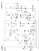
I used an IRFP360 in the simulation, as it was the lowest voltage fet in my collection of models with a size 6 die. Any monster fet with voltage rating of >60V would likely do as well, though some tinkering would probably be needed to get the bias centered.
I would use one of the IXYS depletion mode fets for the current source load for a minimum parts implementation (three active devices - what's not to like?), but a ring-of-two current source with any respectable bipolar transistor and an IRFP140/240 would work just as well.
Food for thought, anyway.
Attached is the fake SIT kernel of the previous circuit, all on its own and fitted with a static current source load. It acquits itself well, with a pretty clean-looking 0.4% THD, almost all (2nd and 3rd), for ~1W output. Remember, that first Watt is important... Gain is 7.2X, so the amp will need a preamp with gain to sing loudly.
I used an IRFP360 in the simulation, as it was the lowest voltage fet in my collection of models with a size 6 die. Any monster fet with voltage rating of >60V would likely do as well, though some tinkering would probably be needed to get the bias centered.
I would use one of the IXYS depletion mode fets for the current source load for a minimum parts implementation (three active devices - what's not to like?), but a ring-of-two current source with any respectable bipolar transistor and an IRFP140/240 would work just as well.
Food for thought, anyway.
Attachments
I shadowed your work in this thread with interest by another I entitled "Other Uses of Vaccum Tubes" in the Everything Else forum. I reported in post#104 above a curious sonic improvement I stumbled on. It led me to propose a transient experiment which is depicted in its attendant attachment. It is another feedback loop from the Drain [post coupling cap] to the Source of the output MOSFET by using the loudpeaker as the feedback element. I hope that you consider doing this experiment and share your results.Attached is the fake SIT kernel of the previous circuit, all on its own and fitted with a static current source load. It acquits itself well, with a pretty clean-looking 0.4% THD, almost all (2nd and 3rd), for ~1W output. Remember, that first Watt is important... Gain is 7.2X, so the amp will need a preamp with gain to sing loudly.
I used an IRFP360 in the simulation, as it was the lowest voltage fet in my collection of models with a size 6 die. Any monster fet with voltage rating of >60V would likely do as well, though some tinkering would probably be needed to get the bias centered.
I would use one of the IXYS depletion mode fets for the current source load for a minimum parts implementation (three active devices - what's not to like?), but a ring-of-two current source with any respectable bipolar transistor and an IRFP140/240 would work just as well.
Food for thought, anyway.
Best regards
I grabbed the latest version of the L'Fake (the two-stage version) and tried to audition it in my living room using a bench supply. One side played, the other took off with some horrible 60-Hz tinged racket that I suspect is either oscillation or a ground loop (or maybe a combination of the two). It didn't display this sort of antisocial behavior in the basement, but then it was being driven by an isolated Discman. I may try that in the living room to see if that clears up the problem. My living room outlets are fed with ungrounded post-and tube wiring, which can't help matters. My basement circuits are properly grounded.
I was able to scare up a model for the BSS159, so I did some simulations. I'm moderately pleased with the results for such a simple circuit, especially as the high order distortion procts seem to be down in the mud compared to
2nd and 3rd. I need to take my bench prototype and shift the feedback point to the top of the resistor as in the schematic, instead of at the top of the IR LED - resistor stack. That may clean up the sound a bit.
2nd and 3rd. I need to take my bench prototype and shift the feedback point to the top of the resistor as in the schematic, instead of at the top of the IR LED - resistor stack. That may clean up the sound a bit.
Attachments
Forget that comment (microphonic), you're running so much current that it doesn't matter. But I do know this-- lamps have a positive TC. I'm still trying to explain the behavior that nelson speaks of (midrange hump), maybe the thermal time constant at work?
I remember building a weinbridge oscillator back in the 80s based a simple 3w lamp. Worked great, 0.1% THD, from such a simple circuit, lamp used as a feedback element.
I remember building a weinbridge oscillator back in the 80s based a simple 3w lamp. Worked great, 0.1% THD, from such a simple circuit, lamp used as a feedback element.
Update - I've been looking more closely at gain-phase plots and am concerned that the current edition of L'Fake bottoms out at 0 dB instead of continuing on to a gain less than one. I wonder whether this is an artifact of the gain-phase analyzer (or my setup), or a real problem, as this sort of thing indicates that there is not enough gain margin, such that hooking up the amp to something like a cable and a pair of speakers (reactive load!!!) could cause oscillation problems to rear their ugly head.
Having said that, the time domain response (square wave test) looks quite benign. However, the square wave test was done with a resistive load with short leads.
At any rate, Ill be probably spending some time this weekend at work with the gain-phase analyzer and an amp or two, trying to suss out whether the analyzer or my simulations (which predict all is well) are telling the truth. I have an HP 3575 gain-phase meter at home that I could press into service for point measurements near gain crossover - it might be able to supply an independent point of view. Plugging my ears and doing the square wave test with a speaker and reasonably long cables might also be instructive. I have run into situations where a resistive load is hunky-dory, but the amp in question takes off when hooked to a pair of real speakers ( my "Kingfisher" tube amp is a case in point). That one took some fixing.
Edit - the time domain and frequency domain plots I'm citing are at posts 108 and 109 in this thread.
Last edited:
This afternoon, I ran a gain-phase plot on the most recent version of the "Fake SIT" amp. The results are appended. On both plots, gain is 8 dB/div, and phase is 45 degrees/div. Zero dB and zero degrees are both in the middle of the page (there are 10 vertical divisions, so the zero point is 5 boxes up from the bottom of the plot).
The bottom plot of the two shows gain and phase for the original amp. The gain (top trace) never reaches 0dB (it even peaks up a bit) before the phase (bottom trace) hits rock bottom, which is disturbing. This is in spite of the square wave response looking reasonably decent. This is an indication of an oscillation problem waiting to happen. Behavior like this explains why some amps might look benign on the bench, but take off and sing like a tree full of birds once they're hooked up to long cables and speakers. Another characteristic of a marginally stable amp appears to be excruciating sibilants, especially on voices.
The top plot shows the same amp with a 33nF + 10 ohm Zobel network hooked across the output terminals. The gain now passes cleanly through 0dB, and stays below it. There is only 39 degrees of phase margin, but that can be (and will be) amended with a change in compensation, now that the amp is behaving itself around the zero crossing. I intend to examine all my amps this way in the future.
This investigation also points out why an output Zobel network is a good idea.
Attachments
Last edited:
I just picked up some 1000W linear quartz-iodine bulbs on fleabay that should prove useful for biasing up a L'Fake Lite at a supply voltage that should offer more efficiency/less wasted dissipation. We'll see how they look when they arrive. I won't spend much time on this for right now, as there are several other projects I want to finish for this year's Burning Amp. I will at least throw a bulb on a bench supply to determine the 2A bias point.
Just to stir the pot a bit, here's a zen-sh fake with a modulated current source load. Gain is about 5X, and THD appears too be a fairly linear function of output voltage, dominated by 2nd and 3rd. The results shown are a simulation with 1V input drive. A 0.2V input signal gives me 1/5 the THD, with a similar harmonic distribution. In practice, I would use the IRFP260 for the big output mosfets rather than the 360s shown in the schematic - those were the models I had available in PSpice.
Attachments
hooking up the amp to something like a cable and a pair of speakers (reactive load!!!) could cause oscillation problems to rear their ugly head.
...BTW, none of this sort of squirreley behavior showed up in the simulations
Those peaky loudspeakers and cables again!

- Status
- This old topic is closed. If you want to reopen this topic, contact a moderator using the "Report Post" button.
- Home
- Amplifiers
- Pass Labs
- L'Fake - A Cheap- A** Expedient to Replace the Elusive SIT