At the operating temperature of the lamp in this application, the iodine will sit around bound to some tungsten, doing nothing. Its purpose is to scavenge deposited tungsten off the bulb envelope and return it to the filament via decomposition, and that only happens at much, much higher temperatures.
I may grab one of the higher wattage lamps tomorrow night.
I may grab one of the higher wattage lamps tomorrow night.
Ok, I grabbed a couple of pairs of the Feit Electric 500W normal duty linear quartz-halogen lamps. I saw no need to go for the extra duty "rough service" lamps (one lamp for the price of two), as this application isn't exercising the lamp anywhere near its design limit.
A bias voltage of 25V gets you 1.8A current through the lamp, and a cheerful orange glow, as compared to the dull red glow of the 300W bulb-type lamps with no iodine or other enhancements. Quartz-iodine lamps run hotter than normal incandescent lamps, as they're designed such that the iodine incorporated inside has a chance to do its thing and scavenge evaporated tungsten from the bulb inner surface. An added benefit is that the higher operating temperature shifts the output a little more towards the visible spectrum. Not a consideration for our application, but interesting nonetheless. If you want to eke out that extra bit of bias current, go for 2 X 300W lamps. If you want one lamp, 500W will work more or less, with a little bit less output power.
A bias voltage of 25V gets you 1.8A current through the lamp, and a cheerful orange glow, as compared to the dull red glow of the 300W bulb-type lamps with no iodine or other enhancements. Quartz-iodine lamps run hotter than normal incandescent lamps, as they're designed such that the iodine incorporated inside has a chance to do its thing and scavenge evaporated tungsten from the bulb inner surface. An added benefit is that the higher operating temperature shifts the output a little more towards the visible spectrum. Not a consideration for our application, but interesting nonetheless. If you want to eke out that extra bit of bias current, go for 2 X 300W lamps. If you want one lamp, 500W will work more or less, with a little bit less output power.
Another Feedback Loop
Allow me to bring your attention to the following. It emanated from my fooling around with the circuit of the last post in the thread which is entitled "Other Applications of Vacuum Tubes" in the Everything Else Forum. Please consult the attached schematic.
Best regards
Hello wrenchone. I have no doubt that you have a great [SIT-like] sounding 12W of output power.I get about 12W output power, scandalous when you consider what's blown in the resistive load plus device heat sink, but then again, it's DIY after all. You can leave the kitchen if you so choose....
Allow me to bring your attention to the following. It emanated from my fooling around with the circuit of the last post in the thread which is entitled "Other Applications of Vacuum Tubes" in the Everything Else Forum. Please consult the attached schematic.
- The left part of its view is the output stage which you currently use in L'Fake.
- The right part of its view is an approach you may wish to consider. It shows the output stage of L'Fake using local negative feedback via the loudspeaker. It emanates from the current source port [drain of power output MOSFET], passes through the loudspeaker and terminates at the Source summing junction. Some of us may call it Schade feedback, but I prefer to call it Pass Feedback. Since neither Mr. Schade nor Mr. Pass used/use this style of local feedback around one single power output transistor, I best prefer to refer to it as ANT Feedback; clearly in the abscence of precedence which voids this nomenclature.
Best regards
Attachments
Here's what a 500W, 120V, quartz-halogen lamp looks like with 25V across it - the lamp is drawing 1.8A, and looks pretty bright. The lamp holder you see may be available in a well-stocked hardware store. I got mine off Ebay, as I've been busy/lazy lately(take your pick).
Attachments
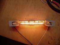
wrenchone, the yellow- orange glow is eye-pleasing. That is a hefty idle amperage flowing through it.Here's what a 500W, 120V, quartz-halogen lamp looks like with 25V across it - the lamp is drawing 1.8A, and looks pretty bright. The lamp holder you see may be available in a well-stocked hardware store. I got mine off Ebay, as I've been busy/lazy lately(take your pick).
Here is the next incarnation of L'Fake, slightly rearranged and with fewer parts. It made encouraging noises when I fired it up in the basement and fed it with a CD player. I'm hauling the carcass in to work tomorrow to tweak the compensation and do a gain-phase plot. The compensation cap will go across C15 - there's none at present.
Attachments
wrenchone,
I have a few questions, if you dont mind.
Is that a mosfet current mirror you are using as a load for the output? I am not sure this is the case due to the different devices, but do not understand the influence of Q5 on Q3.
THe ZVP33 is just a driver for the mosfet output(q2), correct?
It also looks like the output(q2) is schaded. Is bringing feedback from the output a way of schading input or is it just standard feedback. I hesitate to think it is CF, even though it is brought back to low Z source leg of input Jfet, but I am still a little fuzzy on that whole topic. Thanks. I enjoy your circuits because they make me think, as they are not often obvious for someone like me.
There's nothing wrong with an asymmetric current mirror. Both the ratio of the device sizes and the source resistors can be used to impart current gain. I use this concept a lot in my circuits. The input mosfet (depletion mode, BTW) drives both the current mirror and the output Schade pair, and in opposite directions. I originally used another ZVP3306A for the smaller half of the mirror, but changed it to a TO-220 device so I could easily couple it to the heat sink for bias stability. I may change it back if I can find a clever and easy way of coupling it to the output P-Channel. I could use the open loop gain.
The combination of Q2 and Q4 is an alternate way of doing a buffered Schade pair - the previous incarnation of L'Fake showed another. After this afternoon's experiments, I have a little more tinkering in line for the Schade pair, as I have realized that some more open loop gain can be wrung from it while still retaining output voltage centering.
This whole journey started back in 2007 with the "Half Nelson" amplifier, which utilized a Schade feedback mosfet before I knew Schade from a hole in the ground...
")
Hello wrenchone. Glad to see you revived this valuable thread.Here is the next incarnation of L'Fake, slightly rearranged and with fewer parts. It made encouraging noises when I fired it up in the basement and fed it with a CD player. I'm hauling the carcass in to work tomorrow to tweak the compensation and do a gain-phase plot. The compensation cap will go across C15 - there's none at present.
Why would you bother? By adding feedback, you're removing yourself to a significant extent on dependence on the intrisic properties of a given device.
I don't have any R100s anyway (don't plan to get any, either) so I couldn't try it even if I wanted. A better setup might be an R085 with a gyrator or inductive load. That design would benefit from a follower to drive the R085 gate to get around the pestilential gate lakage of the R085. I'll leave that to someone with initiative, as my plate is rather full (my spare time is not).
I don't have any R100s anyway (don't plan to get any, either) so I couldn't try it even if I wanted. A better setup might be an R085 with a gyrator or inductive load. That design would benefit from a follower to drive the R085 gate to get around the pestilential gate lakage of the R085. I'll leave that to someone with initiative, as my plate is rather full (my spare time is not).
Thanks for your post. A SIT is a certain depletion-type JFET which you have already "L' Faked" by using your topololy of Mosfets. I guess you pursued and accomplished this design because current SIT units are rare, as the case is now with R100As. Subtle is the emulation of a complement L'Fake; noting that the loop feedback used in your circuit can potentially render both resulting genders of L'Fake almost identical, and thus useful in other diy Fx circuits..Why would you bother? By adding feedback, you're removing yourself to a significant extent on dependence on the intrisic properties of a given device.
I don't have any R100s anyway (don't plan to get any, either) so I couldn't try it even if I wanted. A better setup might be an R085 with a gyrator or inductive load. That design would benefit from a follower to drive the R085 gate to get around the pestilential gate lakage of the R085. I'll leave that to someone with initiative, as my plate is rather full (my spare time is not).
Your circuit has great potential.
The R085 circuit I mentioned would not have any Schade/partial feedback, so it would be more apt to exploit the intrinsic characteristics of the device, more in line with the usual Pass Zen aesthetic. Some global feedback could possibly be used if there was excess gain, and this would be made easier by the source follower drive to the R085 gate. Unlike some of the circuits shown here, this one could be pretty straightforward. Hint - use a J175 P-channel fet for the follower.
Last edited:
- Status
- This old topic is closed. If you want to reopen this topic, contact a moderator using the "Report Post" button.
- Home
- Amplifiers
- Pass Labs
- L'Fake - A Cheap- A** Expedient to Replace the Elusive SIT