Here’s my first brainstorm. My goal is to achieve around 100 watts with a 750 watt supply. I will be feeding this amp with a 10vrms audio signal from a Balanced Zen Line Stage amp.
I’ve also been told that using CCS pull-ups in the SOZ design lowers the damping factor, in an attempt to compensate for this, I’ve added feedback resistors R3 & R4, however, I still haven’t worked out a good value.
The big question, will I get a good sound out of this design?
I’ve also been told that using CCS pull-ups in the SOZ design lowers the damping factor, in an attempt to compensate for this, I’ve added feedback resistors R3 & R4, however, I still haven’t worked out a good value.
The big question, will I get a good sound out of this design?
Attachments
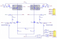
OOOPS, I just re-uploaded the hi-res version of the schematic, the low res 1 was in there. HIRES:
http://www.diyaudio.com/forums/attachment.php?s=&postid=255760
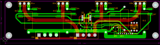
The design uses 2 diferenc CPU modules, though, each module has the same circuitry, the software is a little different.
The goal of "AMP_BIAS_CPU1" is to optimize the Drain bias voltage of Q1 & Q2. It takes in nets "fb_Q1 & fb_Q2 (in green)" which are divided by 10, (hence the 10K res divided by 1K res down by the cpu module connector), fed to the 2 x 24 bit AD converters. The module will measure the inputs between (v_neg) and (vn+24), which is 24v regulated above the (v_neg).
The module has 2 x 18 bit voltage out DACs which also go between (v_neg) and +24v.
The goal of the "AMP_BIAS_CPU2" is to maintain the CCS1 & CCS2. It operates between (v_pos) and -24v, (v_pos) regulated down with a negative 24v regulator. It will be trying to maintain a 23v level (from the modules point of view) at the (fb_CC1) and (fb_CC2).
The 2 modules working together can startup the amp nice and slow controled manner, + compensate for warm and general temparature drift, + with internal flash memory, they can chart the potential deteriation of a lemmon part.
http://www.diyaudio.com/forums/attachment.php?s=&postid=255760
The design uses 2 diferenc CPU modules, though, each module has the same circuitry, the software is a little different.
The goal of "AMP_BIAS_CPU1" is to optimize the Drain bias voltage of Q1 & Q2. It takes in nets "fb_Q1 & fb_Q2 (in green)" which are divided by 10, (hence the 10K res divided by 1K res down by the cpu module connector), fed to the 2 x 24 bit AD converters. The module will measure the inputs between (v_neg) and (vn+24), which is 24v regulated above the (v_neg).
The module has 2 x 18 bit voltage out DACs which also go between (v_neg) and +24v.
The goal of the "AMP_BIAS_CPU2" is to maintain the CCS1 & CCS2. It operates between (v_pos) and -24v, (v_pos) regulated down with a negative 24v regulator. It will be trying to maintain a 23v level (from the modules point of view) at the (fb_CC1) and (fb_CC2).
The 2 modules working together can startup the amp nice and slow controled manner, + compensate for warm and general temparature drift, + with internal flash memory, they can chart the potential deteriation of a lemmon part.
Propeller hats.....
LOL,") , LOL.... hehehehehehehehe…. Can’t stop laughing.
, LOL.... hehehehehehehehe…. Can’t stop laughing.
I just love designing in electronics. The more difficult the design, the more effort I'll put into it. Pressure, big challenges & proving others wrong also helps.
EG: Thing I’ve done in the last 12 months…
Designed 16 PCBs, 10 already came in, designed a real-time graphics DSP core which drives the first 9, 3 additional microcontroller IP cores, all in Verilog, all fully functional, an entire a-la-carte universal digital video format converter / scaler / video tiller / de-interlace / scan converter / genlock / TBC, it’s software, which runs on the 4 previously mentioned IP cores, 2 new provisional patent submittals to add to my existing 3 patents, and, another 6 new PCBs for audio integration, & now, this little amp just for additional experience.
Can't stop giggling.
My existing patents:
6532008 – stereoscopic / holographic / Holoscopic™ ghost removal.
6088052 – stereoscopic line muting interface.
6058192 – universal video sync enhancer & weak sync recovery.
My 2 new ones are for scaling video in such a manner, that, the final result is twice as good as anything else out there.
Nelson Pass said:You don't by any chance have one of those hats with a
propeller on it, do you?
LOL,
, LOL.... hehehehehehehehe…. Can’t stop laughing.I just love designing in electronics. The more difficult the design, the more effort I'll put into it. Pressure, big challenges & proving others wrong also helps.
EG: Thing I’ve done in the last 12 months…
Designed 16 PCBs, 10 already came in, designed a real-time graphics DSP core which drives the first 9, 3 additional microcontroller IP cores, all in Verilog, all fully functional, an entire a-la-carte universal digital video format converter / scaler / video tiller / de-interlace / scan converter / genlock / TBC, it’s software, which runs on the 4 previously mentioned IP cores, 2 new provisional patent submittals to add to my existing 3 patents, and, another 6 new PCBs for audio integration, & now, this little amp just for additional experience.
Can't stop giggling.
My existing patents:
6532008 – stereoscopic / holographic / Holoscopic™ ghost removal.
6088052 – stereoscopic line muting interface.
6058192 – universal video sync enhancer & weak sync recovery.
My 2 new ones are for scaling video in such a manner, that, the final result is twice as good as anything else out there.
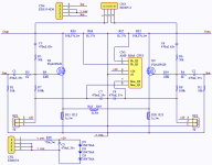
The processor basically does 2 things.
1) it acts like a volt meter. eg: in the main amp section, it will measure the voltage over the 2 speaker outputs.
2) after measurements are made, it will adjust the bias voltage sent to the 2 gates on Q1 & Q2 so that my output is 50% of the supply voltage & the DC voltage difference sent to the speaker is under a microvolt.
In the processor module, there is the potential to store the 2 bias voltages being sent to the Q1 & Q2 gates which will move slightly with amp temperature & age. Downloading this to a PC would give you a graph of your Amps consistency. Sort of like the little diagnostic memory capability in some car's fuel injection system microprocessor.
This concept is not completely new, there are some microcontroler biased tube amps which corect for drift as the tube ages.
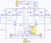
here is the psp...
Nothing special...
Here is the link to my pre-amp / attenuator PCBs.
http://www.diyaudio.com/forums/showthread.php?postid=249002#post249002
Only the Balanced Zen Line Stage left, then I'll have made a complete system.
Nothing special...
Here is the link to my pre-amp / attenuator PCBs.
http://www.diyaudio.com/forums/showthread.php?postid=249002#post249002
Only the Balanced Zen Line Stage left, then I'll have made a complete system.
Attachments
analog_sa said:And why so many bits in the ADC/DAC parts? Seems to me a simple microcontroller with integrated ADC/DAC will do the job. Well, maybe not grow lemons at the same time
Microcontroller ADC are usually sufficient when taking multiple samples, however, I don’t like their accuracy & drift factors. Compare this 4$ 4 channel switchable device: ADS1242
http://focus.ti.com/docs/prod/productfolder.jhtml?genericPartNumber=ADS1242
NOTE: my 2 audio in's go through a 1 Hz low pass filter.
For the dac, I figure 16 bit should be good enough. Something like this:
http://focus.ti.com/docs/prod/productfolder.jhtml?genericPartNumber=DAC8571
Can't use any dacs that need a maintained master clock since I want the processor board to shut down once the calibration is finished.
Now, the cheapest TI processor with 12bit internal AD = 3$, 14 bit internal AD = 7$. Cheapest processor is under 1$. None with a real DAC.
Now, from microchip, cheapest processor is < 1$, with 12bit AD = 2$, no 14 bit or above. None with a real DAC.
I figure using an 8 pin PIC12C508 with the 3$ 24bit ADC, and, 2 x 16 bit dacs (3$), for a total of 10$, it will kill the 7$ ti processor with the 14 bit AD before finding a 2 DACs for it.
Might want to have a peek at atmel.
Typically a tad bit more expensive than Microchip, but a lot nicer IMO. Much nicer instruction set, lots of registers, less funny issues with memory allocation and tables and stuff.
I'm definately far from being an expert on the things, but from the little bit I've done, I've found my favourite.
l8r.
Arx said:Might want to have a peek at atmel.
Typically a tad bit more expensive than Microchip, but a lot nicer IMO. Much nicer instruction set, lots of registers, less funny issues with memory allocation and tables and stuff.
I'm definately far from being an expert on the things, but from the little bit I've done, I've found my favourite.
l8r.
Too later, the design is finished, look here:
http://www.diyaudio.com/forums/showthread.php?postid=257957#post257957
- Status
- This old topic is closed. If you want to reopen this topic, contact a moderator using the "Report Post" button.
- Home
- Amplifiers
- Pass Labs
- Rough draft, modified SOZ with CCS pull-ups & CPU biasing, need advice.