Thanks, dbear44!
Once the bridges are done, next on the list would be to bump C102/C202 to 470µF as in the Threshold 400A. These caps are noted as non-polar on the schematic so I still have to decide whether it's Mundorf ECap Raw or Muse ES. Unfortunately, I have yet to find any film cap that would fit in that space - the Mundorf at 25x38 barely
I am really anxious to replace those too as soon as I can get a parts order together. I will probably use Muse ES or Silmic II. I have no experience with the Mundorf E caps. Looks interesting. PCX has the 400uf on clearance now for 70% off so might be worth a try if the will fit.
For C110/210 I used Wima MKS 10uf@50v (Mouser part# 505-MKS210/50/20 ). These are great for replacing old electrolytics and tantalums as they will fit in many but not all situations. I buy them by the dozen.
for C112/212 there was a 1uf with a .47uf in paralell on the back side of the board. I replaced it with a 1.47uf Wima.
The IXYS bridges I got from PCX. I used VBE 26-12 NO7 which is rated at 32A and 1200V. This is probably way overkill since with the soft start circuit they are never stressed, but the price is not much different from the smaller ones so why not.
I can't say that it made much difference with the old cans. I think it is more like icing on the cake. If the cake is old and stale the best icing in the world isn't going to help much!
Which brings us back to those big cans. What condition they are in depends on a lot of factors. Was the amp used regularly or in storage for years? Was it kept in some hot attic or damp basement or unheated garage? My amp had not been used in years so maybe that is why I needed to change them. YMMV.
I do know that I tried bypassing them with .47uf Wima's (the only thing that I had 4 that matched) and was not happy with the results. The sound became bright and edgy on top while still being soft and congested in the rest of the range. I ended up taking them out. What was happening was when you put a very small value low ESR cap in paralell with an extremely large high ESR cap you are making a filter. The bypass only helps on the high frequencies leaving lower ones still straining to get current.
So what I am saying is if your cans are in OK shape you may be able to get away with bypasses if they are large enough to affect most of the frequency range. If the amp still sounds overly soft and sluggish with the bypasses then you should replace the cans.
Thanks for the confirmation on the IXYS bridges. I was looking at them at PCX as well although my current thinking is more toward building them up with PCBs, most likely the ones Per-Anders makes: Sjöström Audio - RFB03 The high current ultra fast rectifier bridge. This provides more diode options as well as being a reversible upgrade, an important consideration for me.
As for the cans, I did measure them with my low ESR meter and they appeared to be within spec. The question would be whether a low ESR reading is a definitive indicator that the caps are functioning normally and any replacement would not yield significant gains. Since replacement options are limited and costly, it would be nice to know.
The PA-7 to me is a beautiful amplifier. It shares the same Nakamichi design language as their famous cassette decks, and stands out against most other amps at any price range. Everyone else look like electronics, but the PA-7 is art. Adding $200 worth of caps to a $750 amp is a major investment by any measure, but restoring art is very different than merely repairing an amp. So if the PSU can upgrade is as dramatic as you indicated, I'd do it in a heartbeat.
On bypassing, having added the 3.3µF added subtle dynamic differences but the additional 10nF polystyrenes defined the soundstage in important ways, with convincing harmonics from drums, brass and woodwind taking on a palpable dimensionality that did not exist before. No harsh edginess at all.
With the soundstage in reasonably good shape, I am out to fix the bloated bass which some would say is "tube-like warmth". To me, it just sounds like it's trying hard to go lower but can't - like many under-powered tube amps. But the PA-7 has gobs of power, so perhaps changing the C102/C202 feedback cap from 10µF to 470µF will fix that. Or perhaps it's the PSU cans not being able to deliver the goods.
So the question is - did/do you hear the same bloated bass and did your PSU can upgrade eliminate the problem?
With the new cans and 4.7uf bypasses the bass is still a little soft but much better than before. Not the ultimate in grip or slam but still very nice. I'd say that overall the sound is much like a fine high powered tube amp. I'd definitely try changing C102/202 first. I am anxious to do that myself. I am also going to order some Vishay MKP 1837 series for bypasses.
Also, it has been mentioned changing R155/255 from 1k to 220ohm and R157/257 from 5.5k to 2.2k. Can anyone elaborate on what affect this will have?
Also, it has been mentioned changing R155/255 from 1k to 220ohm and R157/257 from 5.5k to 2.2k. Can anyone elaborate on what affect this will have?
With the new cans and 4.7uf bypasses the bass is still a little soft but much better than before. Not the ultimate in grip or slam but still very nice. I'd say that overall the sound is much like a fine high powered tube amp. I'd definitely try changing C102/202 first. I am anxious to do that myself. I am also going to order some Vishay MKP 1837 series for bypasses.
Also, it has been mentioned changing R155/255 from 1k to 220ohm and R157/257 from 5.5k to 2.2k. Can anyone elaborate on what affect this will have?
Thanks for your input on the cans. I am sensing that it is an improvement but short of shifting the signature of the amp from being quite deliberately "euphonic" to more of the "brutus"-like stance of Threshold amps. Definitely something to think about.
On the R155/255 and R157/257. The schematic shows that R155/255 act on the -60V rail and are ultimately controlled by VR102/202, the bias current setting pots. R157/257 are in the "protector" circuit which sense then mediate the +60 on signal spikes to prevent damage on a rail not designed to handled more.
In addition, I have concerns about the output transistor emitter resistors, R125-138/R225-238, which are located on the other side of the PCB, below the heat sink extension. These are film resistors rated at 2W, not cement resistors commonly found in other amps capable of delivering 300W into 4 Ohms. With prolonged exposure to heat in a thermally confined area, their stability may well be in question after all these years. Any bias or rail voltage/bias increases may exacerbate the problem unless they are also upgraded.
These being pretty dramatic steps, I would also like to know if anyone has actual experience in doing so.
To me, it just sounds like it's trying hard to go lower but can't - like many under-powered tube amps. But the PA-7 has gobs of power, so perhaps changing the C102/C202 feedback cap from 10µF to 470µF will fix that. Or perhaps it's the PSU cans not being able to deliver the goods.
So the question is - did/do you hear the same bloated bass and did your PSU can upgrade eliminate the problem?
My friend and I upgraded three PA-7's and I think it's the feedback caps not the cans.
Those two caps were changed on both of my PA-7's by a friend of mine and it made a world of difference in the bass response. I probably need to open them up and check though because I think he used smaller value than 470 micro farad. (I can't make the values out from the pics I had sent you)
I was thinking of changing the big cans on both mine but my friend who is a technician said they are still fine. He put smaller bypass caps on um.
Last edited:
Those two caps were changed on both of my PA-7's by a friend of mine and it made a world of difference in the bass response. I probably need to open them up and check though because I think he used smaller value than 470 micro farad. (I can't make the values out from the pics I had sent you)
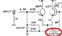
The caps your friend added in one of your amps are 50µF non-polarized. This is what I could make out from your pictures. 50µF would certainly be an improvement over 10µF. According to factory schematics, the PA-5 and PA-7 Mk II's both use a 220µF 16V bipolar in the equivalent positions instead of the 10µF 200V used in the original, and the caps are now C104L/C104R. The Threshold 400A is at 470µF polarized. 470µF would yield a corner frequency of 2 Hz, and this is why I am leaning that way.
Those who have gone down this path before, please chime in - thanks!!
Attachments
The caps your friend added in one of your amps are 50µF non-polarized. This is what I could make out from your pictures. 50µF would certainly be an improvement over 10µF. According to factory schematics, the PA-5 and PA-7 Mk II's both use a 220µF 16V bipolar in the equivalent positions instead of the 10µF 200V used in the original, and the caps are now C104L/C104R. The Threshold 400A is at 470µF polarized. 470µF would yield a corner frequency of 2 Hz, and this is why I am leaning that way.
Those who have gone down this path before, please chime in - thanks!!
Cool thanks! If mine are only 50 then I think I'll up mine too. When you find the caps that fit would you mind posting?
Thanks!
Cool thanks! If mine are only 50 then I think I'll up mine too. When you find the caps that fit would you mind posting?
Thanks!
There are at least a couple of options: the Mundorf ECap Bipolar Raw at 470µF 63V MUNDORF E-CAP AC Series Bi-Polar Plain and Raw Electrolytic Capacitors from PCX; and the Nichicon Muse ES UES1V471MHM Nichicon | Mouser from Mouser. The Mundorf at 25x38 is pretty big and will be a very tight fit for my setup but the Muse ES definitely will fit at a puny 16x25.
In addition, I have concerns about the output transistor emitter resistors, R125-138/R225-238, which are located on the other side of the PCB, below the heat sink extension. These are film resistors rated at 2W, not cement resistors commonly found in other amps capable of delivering 300W into 4 Ohms. With prolonged exposure to heat in a thermally confined area, their stability may well be in question after all these years. Any bias or rail voltage/bias increases may exacerbate the problem unless they are also upgraded.
These being pretty dramatic steps, I would also like to know if anyone has actual experience in doing so.
Thanks ci11. I may try changing the emitter resistors down the road. It looks like you could get at them by removing the heatsink assembly without having to take appart the boards. Here are a couple of suggestions for parts: MOSX5C1R0J KOA Speer | Mouser and https://www.partsconnexion.com/resistors_ohmite_5.html. Any preference of metal oxide Vs NI wirewound? Other suggestions?
Thanks ci11. I may try changing the emitter resistors down the road. It looks like you could get at them by removing the heatsink assembly without having to take appart the boards. Here are a couple of suggestions for parts: MOSX5C1R0J KOA Speer | Mouser and https://www.partsconnexion.com/resistors_ohmite_5.html. Any preference of metal oxide Vs NI wirewound? Other suggestions?
I was looking at these WHS5-1R0JT075 Welwyn Components / TT Electronics | Mouser because they are 5W, cement filled on a ceramic core, and are surge rated. They should be mounted 4mm off the PCB to dissipate power correctly as they currently are.
Well, finally got it done.
I like the sound of the "after" quite a bit: very dynamic, harmonically correct, highly resolving, eerily 3D voices and instruments. So much so that I can almost feel the brass instruments biting into me. And no complex passage could make it sweat. Yet it is also beguilingly warm when the music is properly recorded, just as it can be tuneful, rhythmic or downright chest-pounding if it was in the source. Dead quiet too.
I never thought a 30-yr old amp would sound like this. I remembered when these were around, along with the Thresholds, CJ and ARC, that it was quite rare the music played so convincingly and effortlessly from any amp on any speaker. I've had quite a few come and go, but this PA-7 is definitely staying.
I am now deliriously happy spending much more time listening to a lot more music than digging for the next mod...(famous last words)...
Attachments
I now own 3 PA-5's and 2 PA-7mk2.
I have added a Mundorf ECap Bipolar Raw of 400µF 63V in parallel with C102.
Without added cap (ie. original configuration), gain drops -0.2db at 50Hz, -0.5db at 20Hz and -1.8db at 10Hz.
With the additional 400uF, gain does not drop at 50Hz, 20Hz or 10HZ.
I now believe Nakamichi incorrectly identified C102 as a 10uF, 200V. My recent measurements indicate that C102 is actually 200uF (maybe 10V).
Has anyone actually measured capacitance of C102? Could there be an early version of the PA-5 compared to what I find with my PA-5s?
I suggest that it is change from polarized cap to non-polarized cap that improves the performance, not the increase of capacitance.
I now own 3 PA-5's and 2 PA-7mk2.
I have added a Mundorf ECap Bipolar Raw of 400µF 63V in parallel with C102.
Without added cap (ie. original configuration), gain drops -0.2db at 50Hz, -0.5db at 20Hz and -1.8db at 10Hz.
With the additional 400uF, gain does not drop at 50Hz, 20Hz or 10HZ.
I now believe Nakamichi incorrectly identified C102 as a 10uF, 200V. My recent measurements indicate that C102 is actually 200uF (maybe 10V).
Has anyone actually measured capacitance of C102? Could there be an early version of the PA-5 compared to what I find with my PA-5s?
I suggest that it is change from polarized cap to non-polarized cap that improves the performance, not the increase of capacitance.
A few points:
- I paralleled a Mundorf ECap 470µF/63V Bipolar across C102 in my PA-7 and after the effect is not subtle - more dynamic presentation, more correct spatial delineation (difficult to believe from a electrolytic), and just feels more effortless overall. You can see this in the "after" in Post #31 above.
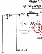
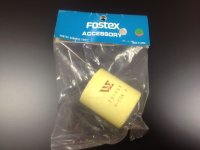
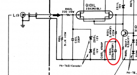
- Before putting the 470µF there, I checked out what is already at C102. It is actually a polyester cap, made by a Japanese capacitor company called U Sigma and is also used in other Japanese manufacturers such as Fostex of car audio and pro audio fame. Please see attached picture - the color of the cap is different but the markings are the same. So it does appear the Nakamichi service documentation correctly stated this part as 10µF /200V.
- But why they picked it over the 470µF as used in Threshold Stasis amps has been the subject of much discussion - the one I tend to believe came from Jon Soderberg who suggested it was likely to "detune" its performance so as not to steal the thunder from the real deal. Having the "correct" value in place certainly elevated the performance of my amplifier.
- James, on the PA-7 Mk II, the feedback cap is C104 and is specified at 220µF/16V so your measurement of 200µF corresponds with their service documentation. Please see attached picture. But the dramatic change from 10µF/200V to 200µf/16V to do the same job in almost the same circuit is a little mysterious to say the least!
Attachments
Outstanding job you did on the PA-7. Just beautifull to look at.
I have the MKII version, it still exactly as it came from the factory and still sounding great.
It never gave me any headache, but due to it's age I'm currently considering a recap and some minor upgrades and your work was an inspiration!
I have the MKII version, it still exactly as it came from the factory and still sounding great.
It never gave me any headache, but due to it's age I'm currently considering a recap and some minor upgrades and your work was an inspiration!
Well, finally got it done.
I like the sound of the "after" quite a bit: very dynamic, harmonically correct, highly resolving, eerily 3D voices and instruments. So much so that I can almost feel the brass instruments biting into me.
I have upped my preamp game (I've "gone toobz"
 ) so I am thinking about doing the same by finally upgrading my PA-7 (original version).
 I notice you replaced the cans--what did you end up going with? The cans that @dbear44 used earlier in the thread are of course sold out, and I did find a Nichicon 33,000μF cap that is a bit smaller than the original (still 100 volts, but envelope size smaller: 51mm x 140mm).
I also found a Nichicon 47,000μF cap, 100 volt, sized 63.5mm x 140mm (where the "6 inches high" spec earlier in the thread is about 152mm). Since the envelope size would fit, would there be any harm in adding that extra capacitance? I wouldn't think so, but I also don't want to change the character of this amp. Cost is more, of course (~$69 each vs. ~$54).
The C102/C202 change to 470μF is definitely on my to-do list. In fact, I may even do that before a full-grown upgrade, as I feel the bass is good but not what it should be.
As far as replacing the smaller caps mentioned above, and the bias pots, does that require a complete disassembly, or can they be done with the boards in place?
Congratulations on your new preamp. I think you will find a refreshed and tuned PA-7 worthy of "toobz".
So to answer your questions:
The cans I used are United Chemi-Con 32D 39,000µF 100V rated at 105°C. Their 63.5mm diameter fit into the original clamps perfectly and work quite well. Took a while to get but well worth it. The ones I got are Made in the USA at the former Sprague plant in NC. I would be cautious of higher capacitances only because the 4 soft-start cement resistors may fry when the higher inrush current demands of the larger caps cause them to overheat. For this very reason, I also stayed with 15A rectifiers and did not go to 30A - it's a balancing act and I prefer to be on the safe side.
The C102/C202 change was a good step forward, and once the caps broke in, the sound was fuller yet more relaxed at the same time, if that can be possible. To do this change and the smaller caps did require dismounting the heatsinks from the main chassis to gain access. It's just easier and less prone to problems since many of the traces did lift off the PCB in the process of desoldering, and it would be impossible to ensure their integrity without full access, These older PCBs did not have very thick traces and require close attention.
Two components I would check closely while you have the PCB/heatsinks off the main chassis are the speaker output relays which are at the very bottom of the PCB - they are subject to incredible heat over the years and get weak, then arcing happens and it's not fun to get back in if you found out they failed when you had them open. The other ones are the output emitter resistors - there are 16 of them and if they look off-color or brown, they should also be replaced. The originals are 2W but I'd go to a full 5W just in case.
It's definitely a labor of love, and I enjoyed the process as much as I did the end result. I hope this is helpful, and good luck.
I have upped my preamp game (I've "gone toobz"
I notice you replaced the cans--what did you end up going with? The cans that @dbear44 used earlier in the thread are of course sold out, and I did find a Nichicon 33,000μF cap that is a bit smaller than the original (still 100 volts, but envelope size smaller: 51mm x 140mm).
I also found a Nichicon 47,000μF cap, 100 volt, sized 63.5mm x 140mm (where the "6 inches high" spec earlier in the thread is about 152mm). Since the envelope size would fit, would there be any harm in adding that extra capacitance? I wouldn't think so, but I also don't want to change the character of this amp. Cost is more, of course (~$69 each vs. ~$54).
The C102/C202 change to 470μF is definitely on my to-do list. In fact, I may even do that before a full-grown upgrade, as I feel the bass is good but not what it should be.
As far as replacing the smaller caps mentioned above, and the bias pots, does that require a complete disassembly, or can they be done with the boards in place?
Congratulations on your new preamp. I think you will find a refreshed and tuned PA-7 worthy of "toobz".
So to answer your questions:
The cans I used are United Chemi-Con 32D 39,000µF 100V rated at 105°C. Their 63.5mm diameter fit into the original clamps perfectly and work quite well. ...... It's definitely a labor of love, and I enjoyed the process as much as I did the end result. I hope this is helpful, and good luck.
Very helpful, yes! The hard part in this is first deciding which parts to replace, where I have to make my own bill of materials ahead of time to sort things out.
I've seen those Chemi-Con caps, and in fact there is a 33,000µF version but is probably too small in diameter to fit the clamps, plus the lead spacing might throw off the bolted connections on top as well.
Good point on those soft-start resistors. I'm not as familiar with circuitry as I should be (much of what I learned was decades ago, and much of it forgotten by now), although it could be tempting to bump up the rating on those also. But on the other hand, why create more work for myself?
I wonder if those speaker output relays are a common item--I would be tempted to just order in a set and replace them as a preemptive move.
I would just ship this out and have it refurbished, but I am not comfortable shipping it more than halfway across the country. (Although I do have the original carton.)
The only thing I can say is that it was more involved than I thought, and I did months of planning before "going in". Even then, there were still surprises.
For one, there were several versions of the boards and the schematics do not necessarily match up. I had to really look and trace hard to get it right. Some parts were simply not there while others showed up "uninvted". With that said, the speaker relays that fit MY boards have a part number of JW1AFSN-DC24V-F and it took me months to find them since they are a replacement for an obsolete part. YMMV.
On the soft start circuit, there is more to it than just the cement resistors - they have in inline fuse heat shrunk to them. So if you were to replace the resistors, you would have to fit a matching fuse, then heat shrink them together. It was one of the more interesting piece of "engineering" I've come across. While you are on that board, you might as well replace the spark arrest cap.
If you are getting the idea that this required quite a deliberate effort, I am being successful in imparting that view. I still don't think how they made this intricate yet heavy thing and sold it for $1,599 back then. They must have paid those dedicated workers peanuts.
All told, the planning was months, the work was several days. But it is my work, it is my amp and I love it.
Very helpful, yes! The hard part in this is first deciding which parts to replace, where I have to make my own bill of materials ahead of time to sort things out.
I've seen those Chemi-Con caps, and in fact there is a 33,000µF version but is probably too small in diameter to fit the clamps, plus the lead spacing might throw off the bolted connections on top as well.
Good point on those soft-start resistors. I'm not as familiar with circuitry as I should be (much of what I learned was decades ago, and much of it forgotten by now), although it could be tempting to bump up the rating on those also. But on the other hand, why create more work for myself?
I wonder if those speaker output relays are a common item--I would be tempted to just order in a set and replace them as a preemptive move.
I would just ship this out and have it refurbished, but I am not comfortable shipping it more than halfway across the country. (Although I do have the original carton.)
Hi Wildcat,
Since I worked on these amps under warranty, I read on and looked in horror with what went on here. To be perfectly honest with you, leave the filter capacitors close to the same values they are right now. Bigger caps will not increase bass and do most of what has been claimed. If you want to, increase by 20% at the most. The soft start resistors will be fine. Some of the modifications are just plain stupid. Most of them make the protection circuit less aggressive, but this was only a problem with the PA-7 while driving stupid speakers. The factory supplied modification package is a couple small PC boards soldered to each channel. The number of folks who actually got any benefit from this was minuscule. Got some nasty Ohm speakers? Okay, do the mod. If not, you're messing up a good amplifier.
The rest, the offset pot is not required. If you have DC offset problems, the diff pair is shot and needs replacement. The huge capacitor across the nice film feedback cap (to ground) just messes things up, it doesn't add any bass. None. The rest of the changes in the "mod schematic" are just playing with the protection network.
If you want to replace some of the smaller electrolytic capacitors, just keep the values the same and work carefully.
If you want to replace the speaker relays too, that makes some sense. Go right ahead with that.
What I can't believe are so many completely unqualified folks making changes to a product that was highly engineered - properly. No, you guys do not know more than the engineers that created these amps.
-Chris
- Home
- Amplifiers
- Pass Labs
- Nakamichi PA-5 upgrades