Hello!
I was in the process of building an Aleph 5 amp, but reading and discussions with forum members(thank you folks: 6L6, Zen Mod, Jacco Vermeulen and Nelson Pass) converted me to make an Aleph 60 instead!
Here is a thread about Aleph 5 for reference(I can delete it after):http://www.diyaudio.com/forums/pass-labs/205621-yet-another-aleph-5-a.html
These are what I have:
1) Chassis: 2 monoblocks with(per each): 2x 210mmX300mmX40mm 0.2c/w heatsinks, 0.19(~5mm) face, 0.125(~3mm) back, top and bottom.
(Will assemble and upload photos soon, waiting for some screws from "online").
2) PSU: 600VA, 25V 2x12A toroidals and 4/ch 100k uf 50v United Chemicon caps.
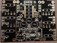
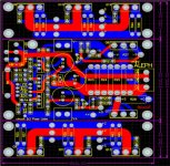
3) BrianGT aleph boards(photo bellow).
I will be using ZVP3310 as inputs and IRFP240 as outputs, which I will order(as soon as he has them in stock) form other forum member — h-a.
Right now I have couple of questions which stops me and would really appreciate your help:
1) Which wires should I use for high current(non signal) purpose? Will any (from let say ebay) 12-14awg with teflon insulation work or you can recommend something better?
2) and major. I have an pdf(sorry can't upload excel, so include a link on it) file attached with schematics, board layout and parts number for the boards I have. I've tried to match parts number from this list to original schematics, but still have many gaps. I would appreciate if you be so kind to help me with this, because I can't proceed without knowing this correspondence. Please!")
Thank you in advance!
https://dl.dropbox.com/u/12499320/Aleph60.xls
https://dl.dropbox.com/u/12499320/Aleph60.pdf
I was in the process of building an Aleph 5 amp, but reading and discussions with forum members(thank you folks: 6L6, Zen Mod, Jacco Vermeulen and Nelson Pass) converted me to make an Aleph 60 instead!
Here is a thread about Aleph 5 for reference(I can delete it after):http://www.diyaudio.com/forums/pass-labs/205621-yet-another-aleph-5-a.html
These are what I have:
1) Chassis: 2 monoblocks with(per each): 2x 210mmX300mmX40mm 0.2c/w heatsinks, 0.19(~5mm) face, 0.125(~3mm) back, top and bottom.
(Will assemble and upload photos soon, waiting for some screws from "online").
2) PSU: 600VA, 25V 2x12A toroidals and 4/ch 100k uf 50v United Chemicon caps.
3) BrianGT aleph boards(photo bellow).
I will be using ZVP3310 as inputs and IRFP240 as outputs, which I will order(as soon as he has them in stock) form other forum member — h-a.
Right now I have couple of questions which stops me and would really appreciate your help:
1) Which wires should I use for high current(non signal) purpose? Will any (from let say ebay) 12-14awg with teflon insulation work or you can recommend something better?
2) and major. I have an pdf(sorry can't upload excel, so include a link on it) file attached with schematics, board layout and parts number for the boards I have. I've tried to match parts number from this list to original schematics, but still have many gaps. I would appreciate if you be so kind to help me with this, because I can't proceed without knowing this correspondence. Please!
Thank you in advance!
https://dl.dropbox.com/u/12499320/Aleph60.xls
https://dl.dropbox.com/u/12499320/Aleph60.pdf
Attachments
I see which parts I need according to the pdf(so I technically could just order and populate), but I really would like to understand a correspondence, but I am not vary good in reading pcb layouts. And yes, I do understand that it is maybe to much for asking, but I sad "please!"
I was looking through the schematics from post #4(thanks again Zen Mod!) and can't quite get all the correction :-(. They say that trim's should be all resistors marked in red, which is only R115?!
Another: DC adjustment, is it R106 or R8?
I am totally confused now :-(. Which of these modifications I need for my 25V trans? Or should I just go according to original values?
Another: DC adjustment, is it R106 or R8?
I am totally confused now :-(. Which of these modifications I need for my 25V trans? Or should I just go according to original values?
Oh, sorry. I understand in general(maybe not for tweaking/tuning yet) operation and I guess it is not fair to ask about basics here(there are plenty books on amps design). So I would think that for me it is best to make a first iteration — populate boards and start the amp...and only after play a bit with it to improve my understanding. Does it sound reasonable?

I was looking through the schematics from post #4
Another: DC adjustment, is it R106 or R8
I used a 5k multiturn pot parallel to R14 (392R) to adjust the offset.
As for the number of 1R resistors I would go for the original number and take 6. Of cause doing this you must also use all the other original values.
You can solder the two more resistors a bit higher simply over the four, they are all parallel......
I used a 5k multiturn pot parallel to R14 (392R) to adjust the offset
and why not R8 and R1 (original notation)?
and why not R8 and R1 (original notation)?
R8 and R14+pot do the same .....changes of the resistor value give more or less voltage at the gate uF the Output IRFs. Adjusting them bring the value of the offset to Zero.
But warming up may change the value again.....or when your input Mosfets are not perfectly matched...
And R1 does the trick to keep these changes nevertheless very small!
So R1 is one of the perfect ideas of Nelson to minimize the offset changes!
R8 or R14 only bring the offset in the beginning or after an hour near zero but do not avoid the small changes over the time that can go up to 100mV.
R1 makes a kind of automatic minimizing the offset changes all over the time......
R1 is experimental, you start with the recommended value of some megohm and you observe the offset.....for instance when it is beginning with around 10-20mA and stays in this ballpark after some time you have won...
if the value is still too great you start to change....... make it bigger and smaller and see the effects direction coming to the goal of 10-20mV at the output. You stay with this value.
Works really fine and if the input Mosfets are closely matched you even do not need the pot I mentioned or any change of the other mentioned resistors.....
good luck....
I do the same at the moment, I use this Mosfet input stage to drive two Semisouth and I prefer the sound at the moment over the 2SJ109 input stage.....
not so detailled, but simply more sound.......! I like this kind of mosfet bloom!
Last edited:
I am about to order at mouser; thermal paste:
I have some from CPU/cooler combo, is it good, or it is better to order this:120-2 Wakefield | Mouser (or some other from mouser)?
I have some from CPU/cooler combo, is it good, or it is better to order this:120-2 Wakefield | Mouser (or some other from mouser)?
- Status
- This old topic is closed. If you want to reopen this topic, contact a moderator using the "Report Post" button.
- Home
- Amplifiers
- Pass Labs
- Aleph 60 building thread