Thanks! But I have -50mV, not +50, will this trick work foe me?
Ok, guys, I have a bigger problem -- There is only 4V between -V and -G on the board (and negative daughter boards, respectively). Everything is ok(~28v) on the positive side. PSU gives 33V to the board.
Any ideas? Could I damage input transistors while soldering? I really need your help as it is my first ss DIY serious amp!
Any ideas? Could I damage input transistors while soldering? I really need your help as it is my first ss DIY serious amp!
well at 10:45 last night you were power up the supply, and now I see a almost done amp...You had to be hard at it to get to this point, now take a break and watch a football game. Think about it and come back. Then start with all wire connections.
Meanwhile the thread will get some replies on where to look, also
Steve
Meanwhile the thread will get some replies on where to look, also
Steve
Here is my own example of finding problems after a night of "putting it all together" It was simple, ground wire wrong place, seems kinda funny now. It worked on the bench, and then.....
http://www.diyaudio.com/forums/pass-labs/2001-mini-82.html#post3090775
Now it runs smooth. We have all had those days.
")
Steve
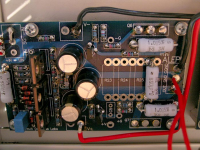
Do you have 9V across Z5?
http://www.diyaudio.com/forums/pass-labs/2001-mini-82.html#post3090775
Now it runs smooth. We have all had those days.
Steve
Do you have 9V across Z5?
Last edited:
Hm, or there should be 4.8V between -G and -V as it is exactly voltage drop on R14(18).
The thing is, it is extremely quiet even with my pioneer hpm which are 95db sensitive...
Another, i run it for an hour(played led zeppelin 2,4) and it is not even close to the temperature i expected, it is like 40-45C max. Voltage across source resistors 0,34V(should be .37V according to A60 schem.)
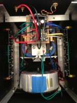
I zoomed into your picture around the RCA connection, i do not see the jumper in place, did you connect on underside? I do not have pcb in my hand but you should need to jumper -In to InG, IIRC
This would increase the volume for sure!
Look here for single ended:
This would increase the volume for sure!
Look here for single ended:
Attachments
Last edited:
Yeah, -In should be jumped to SG....
grab a test lead and touch to the pad, should be sweet music!
I ran mine with test lead in place for several days while bench testing the amps (clipped over the edge of pcb) finally built a proper XLR-RCA cable. I should very soon finish my balanced pre-amp so no need to run it crippled anymore!
Hope you get it running, and enjoy a good nights sleep.
Steve
I was listening the amp for 3-4 hours and that what I get:
1) Need a heatsink for input transistors. I use ZVP3310 in TO92 case and standard small heat sinks I bought just useless. The transistors avery HOT!
2) Bias. I measure voltage drop on a 1ohm source resistor and get 0.32V after couple of hours of operation. That gives me 6x0.32=1.92A of bias. The heatsinks are cool so, I will put a pot instead of R19 and rise the bias.
I have a big question what to do with current gain?
I read these threads:
http://www.diyaudio.com/forums/pass-labs/3589-aleph5-works.html?highlight=Aleph+bias+increase
http://www.diyaudio.com/forums/pass...-aleph-2-a.html?highlight=Aleph+bias+increase
http://www.diyaudio.com/forums/pass-labs/8727-upping-bias-aleph-2-a.html
And A30 schematics ZM attached above.
However, I do not understand is I need change a current gain after I change bias and can I do it without 1khz sine into the input of a given amplitude.
So, I understand that current gain affects the sound of the amp a lot, but do not get when and how to set it.
I would appreciate any comments and clarifications!
well , for current gain , there is no other way than to measure it and then, if needed, set it to desired amount
read what Pa sez for AC gain :
Proper Current Source Adjustment - diyAudio
read what Pa sez for AC gain :
Proper Current Source Adjustment - diyAudio
Post #3
I'm not sure that the quote addresses the question. I
interpret it as wanting to know how to set the current
gain of the Aleph current source, not the DC bias.
For the former, you generally want to set the gain so that
the AC variation of the current source is about 1/2 the output
current. It can be more or less, but 50% gives the optimal
energy efficiency figure.
You will note in the Aleph schematics that the Base of the NPN
transistor which controls the current source attaches to the
output of the amplifier through an RC network. The value for
C is set arbitrarily high so that it does not interfere with audio
frequencies, and it is the value of R which is the most convenient
spot to adjust the gain of the current source. For the purpose
of this discussion, I'll call it R0.
If you set the amplifier driving a sine wave into a load (let's say
16 Vrms into 8 ohms at 100 Hz), you can measure the current
variation of the gain N channel Mosfets (whose Sources attach
through power resistors to the - supply rail) with a cheap AC
voltmeter placed across one of these Source resistors. With
R0 taken out of the circuit, you will get one AC value across the
Source resistor (say 470 mV, for example). As you put a value
for R0 in the circuit, this will decline, and when it measures 1/2
the value without R0, you have reached 50%. If it measures
1/4 the value, the current gain of the Aleph source is 75%, and
this figure is too high for a standard Aleph. Most listeners like
the Alephs at 50% or lower, so I recommend between 50% and
100% of the AC voltage value compared with no R0.
As I understand it is set up to be 50% with 1501R resistor, but if I change the bias up to 30-40% will it change AC current gain, or I can leave it as is (or maybe just take a risk and change it without measuring, according to some extrapolations for other cases?)?
ZM, thanks a lot, is there any song you want me to play on the amp to thank you after I we done?
ZM, thanks a lot, is there any song you want me to play on the amp to thank you after I we done?
- Status
- This old topic is closed. If you want to reopen this topic, contact a moderator using the "Report Post" button.
- Home
- Amplifiers
- Pass Labs
- Aleph 60 building thread