Papa,
Back to back zener between gate and source i presumed? Also just curious why do you consider it leaky, looking at SS R100A specs, it is expected that the gate will draw 10mA with Vgs of 2.6V, R100A max gate fwd current is 220mA so at Vgs or 1.2V 0.5mA seems reasonable.
Alex
Back to back zener between gate and source i presumed? Also just curious why do you consider it leaky, looking at SS R100A specs, it is expected that the gate will draw 10mA with Vgs of 2.6V, R100A max gate fwd current is 220mA so at Vgs or 1.2V 0.5mA seems reasonable.
Alex
Update: I change R6 from 10k -> 4.7k and was able to bias idle current to the 1.5A i was targeting, it could still go higher, but i'm satisfied to start characterizing the amp. I don't have JFET buffers, plan on driving direct from my TVC for now.
On the O-scope i could see about 30mVpk-pk ripples from the supply (100Hz according to the FFT) with nothing connected to input or output. I built the PSU board from teabag with 22mF -> 0.27ohm -> 22mF || 22mF (mf = miliFarad) -> amp. i have yet to measure ripples on the supply with 1.5A loads, just trying to get a feel if it reasonable due to PSRR or its due to something else like grounding or the LED reference voltage needs a cap for smoothing.
If anyone else measured the output noise level on the output on their amp do share, just wondering if what i measured is reasonable. ofcourse 30mVpk-pk is just 10uW of power into 8ohms assuming the voltage level doesn't change.
Alex
Nelson,
Thanks for the advice. I supposed I could back down my bias to 1A range as I notice the gate current don't rise much until I exceed 1.2A idle current. I can live lower power class A in my setup.
I only have 3 pairs of SS so I'll get the first channel working, second channel then revisit if the spare of SS is a better fit. Now only if I can buy another pair from someone
Alex
Sent from my C6903 using Tapatalk 2
Update: I swapped out the 2 JFETs (only one with high gate current) and replaced it with another set. Was able to bias to very high current if so desired (unintentionally turn too fast and current shot to 2.3A) back down current to about 1A idle current, measured output voltage offset, was 21V! Turn the offset trimpot P1 all the way to ground but no change in offset voltage at all. Measured gate current, new Q1 measures almost 1mA. Swapped out Q1 for there other good JFET from first attempt. Bias and offset voltage holding steady and nice. Good thing the Vgs measured by Teabag for both sets was very close, less than 0.1V delta. Phew will introduce audio signal next. I only have 1 pair of JFETs left. Hope that pair is fine.
Anyone with a pair to sell please pm me. I'll be hitting the usual suspects as well.
Alex
Sent from my C6903 using Tapatalk 2
Anyone with a pair to sell please pm me. I'll be hitting the usual suspects as well.
Alex
Sent from my C6903 using Tapatalk 2
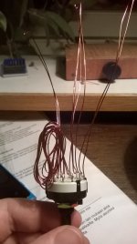
What's this?! its a variable resistor. ")
Explanation: I needed a metod to easily test different degeneration resistor values (soundwise)and sadly the local store didn't have any smaller power resistors (2-3W) than 0.1 ohms. So I made a kind of a lader pot using 0.5mm copper wire. Copper wire resistance is 84.22 ohm/km (for 0.5mm dia) so each 30cm wire length between the switch pins gives about 0.025 ohms additional resistance to the value of R13 and R14. So now I can test the sound of the amp(s) with exact values of: 0.0 - .025 - .05 - .075 - .1 ohms. Will be interesting.
Soundwise thinking: I had the 10 ohm trimpots (P3 & P4) in place and listend for some time. But the problem was that the trimpots would not go totaly open (= zero resistance) so I was not sure how that affected the sound. I've now tried the amp bypassing the trimpots and output degeneration resistors (R13 &R14) but am not totaly satisfied with the sound. With the trimpots in, I got a setting with more flesh and voluminous timber - but also a little too undifiened bass. Without the pots and degenaration resistors the sound is more balanced and tunefull, but... also a little too dry. So now to try the ladder pots.
Attachments
What's this?! its a variable resistor.
Explanation: I needed a metod to easily test different degeneration resistor values (soundwise)and sadly the local store didn't have any smaller power resistors (2-3W) than 0.1 ohms. So I made a kind of a lader pot using 0.5mm copper wire. Copper wire resistance is 84.22 ohm/km (for 0.5mm dia) so each 30cm wire length between the switch pins gives about 0.025 ohms additional resistance to the value of R13 and R14. So now I can test the sound of the amp(s) with exact values of: 0.0 - .025 - .05 - .075 - .1 ohms. Will be interesting.
Soundwise thinking: I had the 10 ohm trimpots (P3 & P4) in place and listend for some time. But the problem was that the trimpots would not go totaly open (= zero resistance) so I was not sure how that affected the sound. I've now tried the amp bypassing the trimpots and output degeneration resistors (R13 &R14) but am not totaly satisfied with the sound. With the trimpots in, I got a setting with more flesh and voluminous timber - but also a little too undifiened bass. Without the pots and degenaration resistors the sound is more balanced and tunefull, but... also a little too dry. So now to try the ladder pots.
I take it is insulated wire? If not then I guess you will have to be very careful none of the wires touch =)
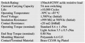
Especially regarding the contact resistance of the switch ;-)...So I made a kind of a lader pot using 0.5mm copper wire. Copper wire resistance is 84.22 ohm/km (for 0.5mm dia) so each 30cm wire length between the switch pins gives about 0.025 ohms additional resistance to the value of R13 and R14. So now I can test the sound of the amp(s) with exact values of: 0.0 - .025 - .05 - .075 - .1 ohms. Will be interesting....
Contact resistance of switch with the silver contacts is about 0.015 ohms (wish I had a better DMM). Also the input leads bring a bit of resistance, but in any case it's better than the 0.15 ohms resistance of the trimpot.
I don't really know if this all matters that much, but as the degeneration resistor values are so small it would be logical to think that minimizing the inherent resistance would make a difference. But it's fun to experiment and try to get the best sound possible in my system. We will see.
I don't really know if this all matters that much, but as the degeneration resistor values are so small it would be logical to think that minimizing the inherent resistance would make a difference. But it's fun to experiment and try to get the best sound possible in my system. We will see.
Attachments
Last edited:
Wierd thing...
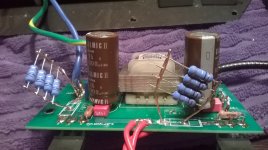
I removed the 10 ohm trimpots (P3 & P4) and changed the caps (as seen in post 5675) . Now one of the channels won't bias up to 1,55 amps - only a little under 1,4 amps. The other goes up, no problem.
Why would that be? Any explanation? Could the new caps be responsible for that?
I removed the 10 ohm trimpots (P3 & P4) and changed the caps (as seen in post 5675) . Now one of the channels won't bias up to 1,55 amps - only a little under 1,4 amps. The other goes up, no problem.
Why would that be? Any explanation? Could the new caps be responsible for that?
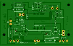
As shown in attached picture (red line).And you made a bridge from the former center position of the pot to the right place?
You do mean R13 and R14?source resistors
I've been testing the sound changing between R13/R14 (0.1 ohm) while the other resistor is bypassed. Also tried both attached with 0.1 ohms to test if the bias would go up - but no.
But still, both channels were treated the same - the other is fine... Also the power supplys (dual mono) give the amp boards 22,67 volts and 22,80 volts. The problem PCB gets the 22.8 volts.
During start up the bias does go over 2 amps but comes down then to the said 1.4 amps.
Attachments
Last edited:
- Home
- Amplifiers
- Pass Labs
- F6 Amplifier