Left seem better and simpler, as extra coil seems unecessary, but i have no idea of coils and whether or not 6 is more easily balanced than 5. I leave it to guru to do his thing. If it improves/changes for positive, what i am hearing, it should be at top of most diy list. Excitement has worn off and it still sounds phenominal.
I have done a "1st-order" simulation of Buzz's circuit from post #4062. By 1st-order I mean that transformer inter-winding capacitances are not modeled. The simulation also assumes exactly matched IRFP240 FETs and other components.
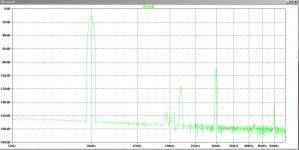
The FFT plots are a follows:
As the plots show, the balanced output successfully rejectes the ripple on the negative rail, but the unbalanced output does not.
The AC analysis shows a serious potential to moterboat, ie. the phase margin below about 5Hz is poor.
The FFT plots are a follows:
- Balanced output: I(Rload) 100Hz, 1 watt across an 8 ohm load.
- Unbalanced output: V(Out+) 100Hz, 1 watt across an 8 ohm load.
As the plots show, the balanced output successfully rejectes the ripple on the negative rail, but the unbalanced output does not.
The AC analysis shows a serious potential to moterboat, ie. the phase margin below about 5Hz is poor.
Attachments
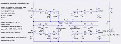
The AC analysis shows a serious potential to motorboat, ie. the phase margin below about 5Hz is poor.
Might want to explore damping that out by loading the outputs to ground
with some resistance.

Might want to explore damping that out by loading the outputs to ground
with some resistance.
I tried adding resistors valued from 10R to 30R from Out+ and Out- to ground. It did not make a significant difference in the AC analysis. I didn't expect that it would.
I found that increasing the Cin caps from 10uf to 100uf eliminates the phase margin problem in the simulation.
I built first one, with FE from second one. Only .1R in source of top fet, with pretty well matched R100's. Feel like simming it? Ill post measurments later. INterestng thing on motorboating. I do not haev amp tied to safety ground in anyway on this Ikebana, and without any thing on output, I have about a 5m-20mV oscillation. I touch the sinks, it cust in half. I load the output with scope or speaker and it goes away.
http://www.diyaudio.com/forums/pass-labs/233101-funny-6-a-6.html#post3441909
http://www.diyaudio.com/forums/pass-labs/216616-f6-amplifier-345.html#post3325340
I will try to measure tonight.
http://www.diyaudio.com/forums/pass-labs/233101-funny-6-a-6.html#post3441909
http://www.diyaudio.com/forums/pass-labs/216616-f6-amplifier-345.html#post3325340
I will try to measure tonight.
Last edited:
I found that increasing the Cin caps from 10uf to 100uf eliminates the phase margin problem in the simulation.
Ha Ha. Didn't notice those....


I am trying to understand the evolution of this thread to talking about a Balanced F6. If we return to Papa's original F6 posting it discusses the highly symmetric nature of driving the output NFETs using transformer coupling. In principle (and reality), this can greatly reduce the 2nd harmonic. In practice, getting (now unobtainium) SemiSouth JFETs that are well matched and dealing with the transformer interwinding capacitances has resulted in underwhelming F6 performance.
Now some are pursuing balanced-F6 configurations. If we wish to go balanced, then everything changes regarding to 2nd harmonic cancellation. There is absolutely no need that the positive rail output fets and their drivers be matched to those on the negative rail. What is needed for 2nd harmonic cancellation is that positive rail fets and drivers be matched on each side and negative rail fets and drivers be matched on each side. But there is no need for matching between positive and negative rail fets and drivers, other than quiescent bias current.
I have some some drawings, math, and simulations to demonstrate this.
This is how mine are arranged. I concentrated on getting lower fets to match well on both sides. The lesser quality matches went on top. They turned out to match pretty well, numbers wise. I cannot justify the balanced version in any way. May be a stupid idea. But to me, it sounds good. Would you be willing to help me take phase measurements with visual analyzer. Also how do you the test for distortion over power band. Is a signal sweep used? I wouldike to provide measured data, but only know how to test for distortion and phase at specific power level. This weekend I hope to listen to balanced f6 vs f5tv3.
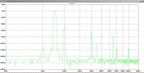
Here is measurements from two channels before bridging
Here is measurements from two channels before bridging
Attachments
Last edited:
I do not understand how the first fft plot could have THD+N = .048%. Something weird is going on there. The 2nd and 3rd plots seem to show THD+N correctly, but the 3rd harmonic seems to be unusually low, visibly absent. That would be great for in balanced amp, which could cancel the 2nd harmonics.
This is how mine are arranged. I concentrated on getting lower fets to match well on both sides. The lesser quality matches went on top. They turned out to match pretty well, numbers wise. I cannot justify the balanced version in any way. May be a stupid idea. But to me, it sounds good. Would you be willing to help me take phase measurements with visual analyzer. Also how do you the test for distortion over power band. Is a signal sweep used? I wouldike to provide measured data, but only know how to test for distortion and phase at specific power level. This weekend I hope to listen to balanced f6 vs f5tv3.
Here is measurements from two channels before bridging
First plot is soundcard only. I bought the MAudio192 to do my measuring.
How can the THD+N measurement in the first plot be plausible?
Might've wrong. What I did was increase output of soundcard until I had 1W across 8R dummy load I then disconnected the amp and looped backed that same signal level into the soundcard with nothing attached. I assumed this would show hat the native distortion mod the soundcard was at that output level. I then hooked up the amp again, double checked power through load, and measured distortion at 1W for each channel. It looked reasonable, with biggest concern being 7k blip on both. One showed higher 4k.
When I get my new boards, ill happily run all test again I you are willing to direct me in how to do so.
When I get my new boards, ill happily run all test again I you are willing to direct me in how to do so.
I might have been wrong about the THD+N figure being implausible. You have 60 Hz harmonic problems, probably due to grounding issues. I see big components at 180 Hz and 240 Hz.
I have had very good luck with minimizing 60Hz ground loop problems using the techniques shown in this thread: http://www.diyaudio.com/forums/pass...ifier-distortion-measurement.html#post2753978.
I have had very good luck with minimizing 60Hz ground loop problems using the techniques shown in this thread: http://www.diyaudio.com/forums/pass...ifier-distortion-measurement.html#post2753978.
Might've wrong. What I did was increase output of soundcard until I had 1W across 8R dummy load I then disconnected the amp and looped backed that same signal level into the soundcard with nothing attached. I assumed this would show hat the native distortion mod the soundcard was at that output level. I then hooked up the amp again, double checked power through load, and measured distortion at 1W for each channel. It looked reasonable, with biggest concern being 7k blip on both. One showed higher 4k.
When I get my new boards, ill happily run all test again I you are willing to direct me in how to do so.

- Home
- Amplifiers
- Pass Labs
- F6 Amplifier