I forgot the question
The dog that I am though...
Unnecesary, i believe.
the two little helpers of Zen Mod.....very skilled electronic men....
gollumgollum

Note in my conceptual schemo there are ports labeled "A" and "B" which should be connected together(A to A and B to B). Also that the secondary phase of the xfrmrs is swapped from N.P.s original design. I have not really given this idea any sim testing or even enough thought.Thanks flg for the schematic. I'll print a paper copy and insert half shaded sine waves to understand its operation. Note that buzzforb and Zen Mod are using only one instead of two Jensens as the principal challenge.
Regarding 1 xfrmr, ideally susy depends on cross coupled MATCHED circuits. Using 2 xfrmrs will likely not be as good as typical fully direct coupled designs (without xfrmrs) or even as good as a design with 1 transfomer. I suppose a xfrmr(1) with the correct winding configuration could be used in the scemo I presented. I was after a simple balanced/bridged configuration of the F6 with Susy.
I may be OT or something
But let's just say we use a(1) 1+1:1+1+1+1 transformer instead of the 2 from the original design you are imagining in my picture. Will it work? Is it susy?

Thanks flg for the schematic. I'll print a paper copy and insert half shaded sine waves to understand its operation. Note that buzzforb and Zen Mod are using only one instead of two Jensens as the principal challenge.
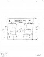
Hurray flg. You have a successful schematic. I used a technique practiced by Mr. Pass to follow a signal bearing a distortion marker[ e.g. an arrow]. Here is how it worked out.
- The Right side amp has a Positive Output; meaning the half-shaded portion of its output sine wave is arbitrarily chosen positive .
- The Left side amp has a Negative Output; meaning the half shaded portion of its output sine wave aims down by comparison.
- Both amps are connected to each other by feedback bridges per flg's schematic; namely via Points A and B. The objective by flg is to allow the Right and Left amps to talk freely to each other.
- Assume that the Right amp develops a sustained distortion. I show this as an arrow aiming downward and emanating from the unshaded negative portion of the output sine wave. The choice of the amp and location of distortion is totally arbitrary technique by Mr. Pass].This is also reflected in Point B which goes to its corresponding Point B destination on the Left amp.
- The arrow pointing down [distortion] in the left amp circuit is applied [fed back from Right amp] to the primary windings of the Jensen exactly like in diyF6.
- Transformer action shows this distortion arrow pointing down at the gate of the upper R100A. It follows that the distortion arrow also points down at the source of R100A.
- Transformer action also shows this distortion arrow pointing up at the gate of the bottom R100A. Since the lower R100A inverts signal phase, then the distortion arrow at its drain also points down like at the source of the upper R100A. .
- The magic of flg's design is at hand. The distortion arrows at the Power Outputs of both amps point down at the same time. The distortion signals are in phase and of equal amplitude. So, this is what happens when a loudspeaker bridges the power outputs. The sine wave signals pass right through; because they are 180 degrees out of phase. By contrast, the distortion signals [current] do not pass through because they are in perfect phase.
Best regards
flg I fully understand your schematic and its potential. I noticed that you suggested a hexfiliar transformer; availability and price may need investigation. Mr. Pass wrote in an early post of this thread that one can also use two independent transformers instead of the Jensen. Your concern may be a mismatched drive [from 2 transformers] to the JFETs. But; it came to light later on that the R100A in diy F6 need not be tightly matched either!. There is leeway.Note in my conceptual schemo there are ports labeled "A" and "B" which should be connected together(A to A and B to B). Also that the secondary phase of the xfrmrs is swapped from N.P.s original design. I have not really given this idea any sim testing or even enough thought.
Regarding 1 xfrmr, ideally susy depends on cross coupled MATCHED circuits. Using 2 xfrmrs will likely not be as good as typical fully direct coupled designs (without xfrmrs) or even as good as a design with 1 transfomer. I suppose a xfrmr(1) with the correct winding configuration could be used in the scemo I presented. I was after a simple balanced/bridged configuration of the F6 with Susy.
I may be OT or something
Will it work? Is it susy?
Operation of Babelfish F6x [BFF6x for short]
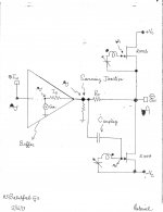
Two unsolicited posts. This one discusses the inner workings of one of two matched amps in BFF6x. A hand-drawn skeletal schematic of this half amp or solo amp [implicit permission from Zen Mod] is attached. Note the following.
I have another post which will show the potential of BFF6x to cancel distortion at its power output ports. It'll be a treatment like I did for flg's schematic in an earlier post. I'll have to hand-draw its skeletal schematic first.
Best regards.
Two unsolicited posts. This one discusses the inner workings of one of two matched amps in BFF6x. A hand-drawn skeletal schematic of this half amp or solo amp [implicit permission from Zen Mod] is attached. Note the following.
- It is totally different in topology from that of diy F6.
- Note the phase of the signals in the circuit.
- The Summing Junction is one very important innovation. The output impedance of the buffer [Zo] has a finite value, and is not zero Ohms. A possible example of this buffer maybe one cell of Mr. Pass's "Beast of a Thousand Jfets".
- Two out of phase signals add up at the Summing Junction and generate an error or difference signal. One signal is from the buffer's internal generator [Gen], and the other out of phase or feedback signal emanates from the power output port. This is a different approach from that used in diyF6.
- This difference signal is presented to the gate of the lower R100A via a high quality coupling capacitor. It is amplified and appears phase inverted at the the drain of this R100A or the output port.
- The above difference signal is also presented to the coil of the transformer. Transformer action thereafter presents it to the coil attached to the gate of the upper R100A. Note its phase. This signal is then processed by the upper R100A, and appears at its source in phase with that generated by the lower R100A.
I have another post which will show the potential of BFF6x to cancel distortion at its power output ports. It'll be a treatment like I did for flg's schematic in an earlier post. I'll have to hand-draw its skeletal schematic first.
Best regards.
Attachments
Thanks Zen Mod. It is a valuable reference. I was interested in DIDO [Diff In Diff Out] in the mid 1970s. The attached shows an example; the author of the book [taught at the University of Illinois] is Fitchen/1970.
Attachments


Also my transportation [poor grad student] to class.
this is ( at least - something as it was ) all in what I was interested in mid 1970s ..........
Sorry buzzforb, I still can't open the attachment on the left. It locks up in a "loading" state.FLG, Antoinel,
What difference is there in these two variations?
this is ( at least - something as it was ) all in what I was interested in mid 1970s ..........
My ride was a Raliegh 10 speed, that I worked and saved every penny for. Until about '75 when I got a '65 VW
A time gone by
FLG, Antoinel,
What difference is there in these two variations?
What he said! I could "Save picture as" and open it but no resolution. Basically, I think the same
Except the phasing is important and I can't see it clearly? It is important to remeber the feedback in F6 is not negative with respect to the input. I don't think I want to call it positive feedback but... Or current feedback but...If your phasing is correct, then I beleive your concept may work, and be more "Balanced" where mine is only bridged and X'ed. It appears to be the same difference seen in the Aleph X amplifier vs the image on the XXX899 patent 1st page.
....... It is important to remeber the feedback in F6 is not negative with respect to the input. I don't think I want to call it positive feedback but... Or current feedback but...
.....
it is veeery negative feedback ; fact that is "unconventionally" connected back to input is piece of puzzle which is saying that you aren't so keen with toob circs ( feedback from out to input cathode)
funny , nobody said that feedback arrangement is exactly the same as in F5 ?
Operation of Bablefish F6x [BFF6x part 2]
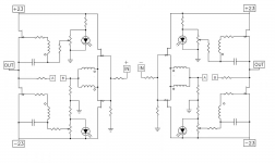
The schematic of BFF6x is attached. Note the following:
Best regards
The schematic of BFF6x is attached. Note the following:
- Suppose the coupling capacitor to the gate of the lower JFET of the Right side amp is poor, and thus expresses a sustained distortion.
- The half shaded sine wave signal showing an arrow point up is a qualitative pictorial of this distortion [a Pass technique] .
- It follows that the resultant power output distortion signal shows the distortion arrow pointing down because the lower JR100A inverts its absolute phase.
- Most importantly, it follows that the distortion signal is also injected in the coil which is attached to the gate of the lower R100A
- Here is the magic of this Zen Mod schematic. The distortion signal is transmitted to the remaining 3 coils via transformer action. Note the phase of the distortion signal at the gates of the remaing 3 R100As, and especially at the power output of the Left side amp. The iron core of the transformer which is common to the four coils is the intermediary which enabled the Right and Left amplifiers to "talk" to each other [share and deal with this distortion].
- The verdict is crystal clear. The distortion signals at both power outputs are in phase, and are of similar amplitude. This power distortion signal will not flow through a loudspeaker which bridges the two power output ports. This amplifier has a unique property of distortion cancellation; absent in the individual or stand alone Right and Left amps.
Best regards
Attachments
pretty much everything as I said ; you can always count on my Dumb Greatness , same as my Spy Bird in FW ( sometime even PL ) cousine ;
maybe Mithrandir ( artist also known as my Pa ) send me that sketch , feeling enooooormous pity - seeing me as fish out of water ( however - my usual state/condition) ?

maybe Mithrandir ( artist also known as my Pa ) send me that sketch , feeling enooooormous pity - seeing me as fish out of water ( however - my usual state/condition) ?
Attachments

Last edited:
- Home
- Amplifiers
- Pass Labs
- F6 Amplifier