......
BTW why do you want to take a complementary pair of SITs and no two SK82? Many of us may have at home....

Attachments
Last edited:
because I have ( well , not exactly "I" , but Bata Bane - he acquired them for rejuvenating his Papa's TA-5650) leftovers - 2+2 pairs ;
whatever - it's easy to accommodate biasing scheme for complementary , taking care of Pa's arrangement (upper ref. to gnd) ; I would still go to both biasing circs based on floating supplies , it's easier to grasp
as I said - it's easy to be smart post hoc
...you guys talking about hindsight ?.....
being portuguese my latin is not so good!....Riding the coattails!
me too...I'm trying not to loose my hold on them ...
I was just trying to get ZM let us know what he's building his nice shiny new Box with Huge heatsinks for....thought it might be something like this ...with Papa SITs he's got !
Last edited:
sorry Zen Mod, I must have mixed up something.....in one thread you were speaking of SK16 (?) and SK60....
G
as I'm saying HERE and HERE , I have some pairs of 2SJ18+2SK60 in drawer ; using 2SK82 is even better (for quasicomplementary iteration) , due to their higher ratings
of course , one must be aware of rank (bias voltage ) of exact VFets one is having on disposition , so accordingly dimensioning bias net ( exact values in final voltage resistive divider
......
I was just trying to get ZM let us know what he's building his nice shiny new Box with Huge heatsinks for....thought it might be something like this ...with Papa SITs he's got !
nice and shiny (gold sinks) will be something (lips sealed ) , while Babelfish SIT-2 will be made in really old school fashion boxes
these two are on shorter rope , I mean - in line before F6 iteration from post #3431
In a past post, Mr. Pass suggested that two separate transformers can be used instead of a quadrifilar. Will this alleviate some of the issues raised above. I am also speculating that one can readily introduce a deliberate and favourable gain assymetry [tranformers not 100% matched], and their reduced interwinding capacitance [by physical separation] will extend the amp's frequency response beyond 5KHz before employing Pass loop feedback.correct , and not correct
facts :
1. xformer windings are quadrifilar ; that means somewhat highish capacitance between them
2.lower secondary is sort of sitting on lower rail potential all the time , while
3. upper secondary is floating with output potential ;
result: that (2 vs. 3) , and fact that upper biasing net is really using it's bootstrap function , is really introducing capacitance issue in game
whatever - as Pa said - that's not an issue if you are aware of it - sonic results of F6 are confirming that
our beta testing guys ( you know who you are ) already gave us primary info about that ; with your chip about flipping places of SS , we know more
your truly , Mighty Boy ZM

joking , off course
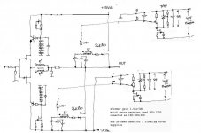
here's quick draw of Sony Vfet complementary F6 concept
time for another public disgrace of Mighty ZM
I'm not going to try it in next ...... 6 months ......... or even later
disclaimer - my main spks are 16 Ohms , so for my needs everything is relaxed , regarding OLG , CLG ,NFB,yukyuk
edit : recommended reading , needed for circuit calc : https://dl.dropbox.com/u/20665608/SONY VFET AES.rar , tnx to RK R
dunno how long it will be there , so down it
editedit : for sorta useful logic for circ calc , see Pa's BA3 article ; scroll down to my comment , where I done all work

Zen Mod: Will there be an electrical problem if one kept the biasing Vgs on all the time in both of your schematics? If no problem, then we will have a simpler execution of your designs.
or Serbiausing two xformers in battery will change things maybe just a little , but that will introduce other complications
gain asymmetry ( different secondary loading ) is already covered in thread
all roads are leading to Rome
Zen Mod: Will there be an electrical problem if one kept the biasing Vgs on all the time in both of your schematics? If no problem, then we will have a simpler execution of your designs.
no problem expected
or Serbia
naah ; it's well known from which neck o' wood is she -wolf
Zen Mod: Thus, the relay circuit is no longer needed, as the the VFets are continuously protected. You may consider installing indicator lights and/or analog voltmeters [ fancy round] to show this status. Better check than sorry!no problem expected
naah ; it's well known from which neck o' wood is she -wolf
I like your designs. They will have the expected intrinsic triodish-like performance; which is further linearized by using Pass negative feedback. Will it be possible for you to show a third schematic whereby the Source ports of the complementary VFets face each other; with focus on their biasing and protection.
Zen Mod: Thus, the relay circuit is no longer needed, as the the VFets are continuously protected. .......
I presume that bias net based delay isn't mandatory at all , but why not puttin few more parts in something Pa is always doing in simplest form ?
there is no way to improve many of his ideas (without transforming them in something completely different ) , except adding bunch of random parts ( l'art pour l'art )
.........
I like your designs. .......Will it be possible for you to show a third schematic whereby the Source ports of the complementary VFets face each other; with focus on their biasing and protection.
most of them aren't mine , but pure Babelfish work ; it just happen that I have pretty crazy and hysteric Babelfish at my disposition , for that work
regarding source follower based OS , it can't be drawn without belonging FE ; it can be made in few different ways , but each of them is excluding use of xformer in signal path ....... you need full gain from FE , using xformer for that role is troublesome (not elegant as in M2 case) , using xformer just for part of gain and rest of active circuitry for rest of gain .... is just not elegant , at least comparing to FW F6 or M2 elegance.
to cut a long story short - I like xformers , but only under condition that they're doing more than one basic thing ; that's why ( at least in this verry moment ) I can't see a place for one in source follower based Vfet OS ;
besides that - using VFets in source follower OS looks as sort of wasting them , at least to my romantic , non-engineer , two cells

Last edited:
Thank you Zen Mod for your valuable thoughts in the above post. I was thinking a BA-3 front end driving a dual secondary transformer with a step up ratio of up to 5. Like the Jensen of F6, such a transformer is/maybe expensive and/or difficult to find. I thought that a source follower OS will not amplify the winding capacitance of the transformer and thus not degrade the frequency response before applying loop feedback. Also, VFet operating in source follower is/maybe not its forte.
I am glad you covered all of the configuration options for the OS. I hope that DYIers working with VFets consider biasing their Gate -Source all the time to prevent inadvertent runaway.
Best regards
I am glad you covered all of the configuration options for the OS. I hope that DYIers working with VFets consider biasing their Gate -Source all the time to prevent inadvertent runaway.
Best regards
Worst case......?
Let us assume I have k2 negative phase in one channel and positive k2 phase in the other......
What will I hear ? No k2 distortion at all? The sound of one hand clapping....?
This could happen if you cannot measure the distortion spectra and the transconductance of your two SS is different and you swap the upper and lower place between the two channels.
One of my F6 channels is now in the neutral state, means k2 and k3 are on the same level. I can change k2 to the positive and negative side.
The second channel still will not do this, I have to swap the SS again and again looking for the right pair...
May be I am too academic today....
Two channels working I will report if I can hear the sound of one hand clapping....!
Last edited:
My guess would be the test suggested in the mosfet testing article by Nelson. I would imagine the differences are in the Ciss and possibly leakage current. ZM eluded to capacitance issues due to interactionwith transformers windings. Based on what Generg and Ilquam have shown, there is some parameter that we are missing that is not seen with basic matching. The SS I have match very well in the general sense, but I have not gone beyond that. Nelson replied to Ilquam on this topic somewhere earlier in the thread, but it might be difficult to find.
Well, lets assume there are plenty of close matched pairs out there.
Working with any one person has already got, some practical experience on which one to place in what position might make it sound better.
I am not certain we can measure that , but we may see consistent subjective performance enhancements by placing one FET here or there.
Generg might have a method in place already.
I don't think measuring leaking current across the gate resistor is a true test of that parameter, but I may have misunderstood my reading on the matter.
If matched at a certain I and Vgs, as most matching is done, you don't know much about yfs similarity. Having a curve tracer, you and I have the ability to see if Yfs is similiar over a greater range of values. I have checked the SS you sent me and they are very good matches. That only leaves differences in gate leakage and other parameters like capacitance. ZM seems to think it is gate leakage or Yfs at first guess. If Generg and Ilquams differences are not the result of different Yfs, then it has to be something else. We do know that putting a fet with lower Yfs up top should enhance the 2nd harmonic, due to the fact that the lower fet is contributing more to the output than the upper fet. I would assume that is what most are looking for. Tweaking this any further would depend on use of Rs and Zen pot. I could be wrong. Wouldnt be first time.
- Home
- Amplifiers
- Pass Labs
- F6 Amplifier