I completed F6 with IRF240's.
I used 1R Source resistors. The bias only went to ~500mv with existing 5K Pot.
Assuming I go, to .5R resistor, I think this will give me enough room to bias higher. I was too scared to add pots across the source resistor. With IRF240's I am not sure if that's a good idea, assuming the overall source resistance goes below <.5R overall.
If not I was considering changing R3-4.
Any thoughts?
is that an optional to220 placement for the 0r1? this may just stop my progress building my own PCB, though I would like 2 or 3 in parallel there since i'm using r125. I have some 0r66 tx220S (older Sfoil version of the Z, but they are 4 leaded) yes I have that many waiting for a project just like this, I love DIYA for sales forums =)
though I may carry on as I want to use some SMD parts for something different (and because I have a large stock of them. a modified all Nchannel front end would be cool too with bf862, but I cant think of how to achieve that.
Last edited:
Tea bag I thought you said the Onetics is in action or is it disguise as Jensen?
Sent from my Xperia Ion using Tapatalk 2
yeah that got me too, first pic on previous page is Onetics, second is Jensen
Qusp,the datasheet is this thread. Just searcg BudPs post. I wonder if a single dcb1 like bf862 FE would have low enough Zout for the trafo. Could always parallel.
thanks mate, will do, was going to PM him but thought i'd check here first. re BF862, apparently 4 in parallel is about as far as you can push them without adding some inductors to stop RF parasitics, but I would expect 4 parallel with a couple little copper BGA heatsinks would make a nice little FE if I can make it work
shoot for 50 max
haha always the jester, though of course being tiny SMD, 50 in parallel could be made to fit in 5cm x 5cm double sided PCB. tempco is pretty neutral, its just the fact they are made specifically to amplify RF, so given the opportunity, thats what they do whether you like it or not.
As always, I am all ears, and looking forward to your results.I finally got all of the parts to try out IRFP240s and FQA28N15s with a new set of Teaser-6 boards.
Stay tuned to this station...
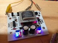
It is gorgeous. I am looking forward to your results.Here is the board without FETs showing room for 2 LEDs. Here I used the red, blue - but swapped to blue , blue. Now it biases over 1v across 1R without an issue.
Who is clever enough with words to have two possibilities.Jester ?

who's Jester ?
I was speaking about buffer out impedance
haha sorry, I thought you were making reference to a certain parallel jfet beast, so thought you were joking about 50x bf862 in parallel for acceptable buffer

let me rephrase my post then:
thanks for the tip!
Ihave gotten hooked on the smd thing as well. Salas RIAA will be made with Vishay TNPW. Too bad they dont make good polysterene caps in SMD. What would be compact board is made large by caps.
i'm sure they do, but they are sure hard to find, probably you would need to get enough people together to get OEM. you can get SMD teflon as well. both of these find their home in high grade RF.
but you are correct, its usually these large film caps that ruin a compact design, however with some planning you can arrange it so that a large cap like that sits directly over a bunch of other components on the PCB, so it doesnt take up any more real-estate, only height
indeed SMD is addictive once you get the taste for it, particularly since there are so many new and quite interesting discrete parts, easier for DIY PCB manufacture, easier rework blah blah, i've said it all before.
You cannot argue with the performance specs of the resistors, that is for sure. Got Toshiba jfets in the RIAA, so it makes hovering caps difficult. I was surprised to find that i could not find an SMD cap that could beat Pana FM, spec wise. None of this takes ito consideration sound of components, but lets not go there or we will all be hating each other by the end of the day Translation to power amps is difficult because with CLass A, you just need space.
Translation to power amps is difficult because with CLass A, you just need space.nosiree, the resistors are outstanding! as an aside, so are the new range of thin film caps (for the very low values up to 22pf, Cdom etc) thats mainly what I will be using, low wattage resistors, BF jfets if I can and probably the LEDs will be SMD. i'm not looking to make the whole thing SMD on this thing, just mixed, its a chunky power amp with manly power jfets, i'm just looking to have a bit of fun with parts I have on-hand. for the low wattage resistors, LEDs and jfets I actually dont think there is a better choice anyway. maybe i'll find some whacky shielded RF board mount SMD connector for the input as well.
the main reason I want to do a PCB is to use up those tx220S 4 lead resistors (I literally have a small punnet full of them on 4 lead 0r66, 4 lead 4R and 2 lead 10R that I got for exactly this type of occasion), which are near useless as far as power ratings are concerned (less than 1W) unless you have them heatsinked (12W), so I need a bit of a unique layout for that section to allow 2-3 in parallel but heatsinked.
^^ before anyone says, I know some are thinking it, i'm aware I could make light work of that aspect with p2p and some thick copper wire, but thats not the point =)
whats the problem with the caps you are finding, leakage currents?
sound of components? I dont know what you mean? =)
Last edited:
- Home
- Amplifiers
- Pass Labs
- F6 Amplifier