Patrick's heatsinks have them side by side so a pair of J74 could be used instead of a J109, on the same pad. For good thermal tracking face to face would be the most logical in this project.
which is why I mentioned it first (but made a pretty obvious mistake), thermal tracking would be every bit as good side by side+opposed if they can use the heatsinks, also allows the current to be increased. its not like the device is anywhere near the face
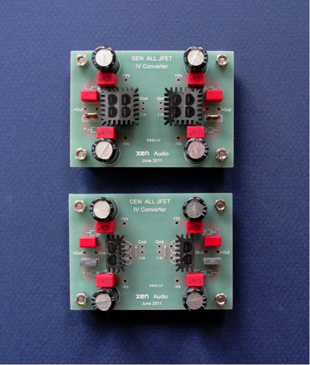
they are not just designed that way so they can replace j109, but also so they can be used in sets of 4 ala SEN/CEN, which has nothing to do with j109
that one
btw. - what's that ?
Sprint ?
Ja, simple operating and sufficient for my demands
or that one?
lhquam, permaneder and Tea-Bag. Your PCBs are great art, organization skills and a test bed for many experiments. Will you consider the following?
- A PCB for Unbuffered diyF6. The concerns of qusp disappear.
- Adding a headphone output which is uncommon in Pass amps. Maybe beneficial for tweaking/balancing the important good distortion.
lhquam, permaneder and Tea-Bag. Your PCBs are great art, organization skills and a test bed for many experiments. Will you consider the following?
Best regards.
- A PCB for Unbuffered diyF6. The concerns of qusp disappear.
- Adding a headphone output which is uncommon in Pass amps. Maybe beneficial for tweaking/balancing the important good distortion.
Hi there,
Mine can be jumpered to not use the Buffering of the JFETs, source resistors for R100's or Toshiba's. In the end I will probably run without them, since my impedance is low from my electronic crossover. But for the initial testing, all parts will go in, and options guided for IRF240's or Fairchild MosFets
A headphone output is a matter of typing the outputs to a headphone jack sharing common ground. Something IMO does not belong on a PCB.
My boards are being built, so changes now are not really top of mind, unless there is a mistake and the board will not work - OR the idea is so brilliant it's worth a re-spin.
Last edited:
Thanks Tea-Bag. I look forward to bying your PCBs, and others from each artist to pursue dedicated applications.Hi there,
My boards are being built, so changes now are not really top of mind, unless there is a mistake and the board will not work - OR the idea is so brilliant it's worth a re-spin.
Best regards.
I like to make power and output connections using hexagonal standoffs attached with #4 (or M3) screws. That allows removing the boards without needing to unsolder anything. Similarly, make the spacing (and size) of the input connections so that a .1" 2-pin header can be used.
Tell me please, what would you like to tweak? I'll try to implement it.
I like to make power and output connections using hexagonal standoffs attached with #4 (or M3) screws. That allows removing the boards without needing to unsolder anything. Similarly, make the spacing (and size) of the input connections so that a .1" 2-pin header can be used.
The connectors on my layout are 6.3mm flat jacks. No desoldering necessary.
2.54mm pin headers are no issue. I could easily change the board, if you like.
Last edited:
do you mind ?
Eer, you an Abacom file collector or actually planning to assemble a Fierst Waff ?
(me no have upsidedown reader with spell check)
http://www.diyaudio.com/forums/pass-labs/216616-f6-amplifier-322.html#post3277123
How do you trimm the 10 ohms pot?
Could a panelpot be used for them?
How do you trimm the 10 ohms pot?
Could a panelpot be used for them?
Of course. Send a PM and I'll mail the file plus the Gerber files
Vielen Dank - files received
Eer, you an Abacom file collector or actually planning to assemble a Fierst Waff ?
(me no have upsidedown reader with spell check)
just handy to have them , from few reasons - neat and simple layout , I have Sprint proggie
will not going to make it ; my heart is still with M2 , as most wakoo Papa's prank

Are any of these PCB being sized to fit the Universal Mounting Spec?
http://www.diyaudio.com/forums/imag...sal/universal-mounting-specification-v2.1.pdf
http://www.diyaudio.com/forums/imag...sal/universal-mounting-specification-v2.1.pdf
lhquam: The center to center spacing between the drains of the R100s in your PCB is estimated at ~3.7 inches. By comparison, the distance in proto F6 by Mr. Pass appears to be ~ twice this value. The junction temperature in the R100s of your design is expected to be relatively higher than that with more physical separation between the R100s. Is hotter better or worser for sound, for the ratio of H2 to H3 etc.?After seeing Tea-Bag's PCB layout, I was inspired to play around with another layout variation. This one is Jensen only and provides some additional options, such as lowered voltages to the drains of the input JFETs.
There is an element of symmetry in the PCBs proposed by you, permaneder and Tea-Bag on either side of a line between the R100s. They are also highly compact. The probability is very low that we will ever learn about anything on the inside of a production F6. Possibly, with the permission of Mr. Pass, one may be able to reproduce a PCB like the one in his proto F6 and compete with the others. Mr. Pass: will this be OK with you?
Last edited:
Heat dissipation is not an issue for such a low resistance. The idle power will be Ibias^2*R. For Ibias=1.5A, and R<0R44, the power will be less than 1 watt.
Which means you can move to 3 watt surface mount foil.
http://www.digikey.ca/product-detail/en/KRL7638-C-R018-F-T1/KRL76C.018CT-ND/1936102
At about $1.5 $2 each, it's no contest. Foil wins, the others do not even need to get out of bed. They should just stay there.... and fade away.
Last edited:
My PCB layout is for 5"x7" fan cooled heatsinks like shown here:http://www.diyaudio.com/forums/pass-labs/216616-f6-amplifier-152.html#post3157489.
lhquam: The center to center spacing between the drains of the R100s in your PCB is estimated at ~3.7 inches. By comparison, the distance in proto F6 by Mr. Pass appears to be ~ twice this value. The junction temperature in the R100s of your design is expected to be relatively higher than that with more physical separation between the R100s. Is hotter better or worser for sound, for the ratio of H2 to H3 etc.?
There is an element of symmetry in the PCBs proposed by you, permaneder and Tea-Bag on either side of a line between the R100s. They are also highly compact. The probability is very low that we will ever learn about anything on the inside of a production F6. Possibly, with the permission of Mr. Pass, one may be able to reproduce a PCB like the one in his proto F6 and compete with the others. Mr. Pass: will this be OK with you?
Thanks lhquam.My PCB layout is for 5"x7" fan cooled heatsinks like shown here:http://www.diyaudio.com/forums/pass-labs/216616-f6-amplifier-152.html#post3157489.
Are any of these PCB being sized to fit the Universal Mounting Spec?
http://www.diyaudio.com/forums/imag...sal/universal-mounting-specification-v2.1.pdf
Yes, @ 120mm from screw hole of power Fets.
Which means you can move to 3 watt surface mount foil.
KRL7638-C-R018-F-T1 Susumu | KRL76C.018CT-ND | DigiKey
At about $1.5 $2 each, it's no contest. Foil wins, the others do not even need to get out of bed. They should just stay there.... and fade away.
taking in account importance of value precision and/or tolerance - plain vanilla Panasonics are more than OK
but I agree - those KRL are sexy looking
( see - ZM as resistor fetishist ; I'm becoming same as Jaccolina )
- Home
- Amplifiers
- Pass Labs
- F6 Amplifier