Potential high OLG for F6 clones.
My thanks again ZM for subtly pointing out the voltage gain of the BA 3 Front End [FE]. I do not know its numerical value; but here is the connection which followed: By comparison with BA 3 FE, the FE of Conceptual F6 has unity gain. So, an OLG much higher that currently attained in the clones of lhquam, buzzforb and others is potentially at hand by replacing the FE in Teaser-6 and Franken6 etc with BA 3 FE.be aware that , without attenuating net , that hunt can be extremely short
and , after that , no further need for any sonic hunt

to tame the BA-3 frontend you could use this variant with feedback....")
http://www.diyaudio.com/forums/pass-labs/201281-burning-amp-ba-3b-balanced-35.html#post3175510
but of course you have feedback in the system now.....
http://www.diyaudio.com/forums/pass-labs/201281-burning-amp-ba-3b-balanced-35.html#post3175510
but of course you have feedback in the system now.....
I am working hard to be as nutz as you. Fat chance! I surely hope that my posts are not confusing. But; I am more than willing to explain further and to any length needed anything I wrote which was not clear to you.@ Antoinel
I'm having slight impression that you're nutz almost as me ........
looking 10 days back , only I posted more useless and confusing posts than you ........
Thanks generg.to tame the BA-3 frontend you could use this variant with feedback....
http://www.diyaudio.com/forums/pass-labs/201281-burning-amp-ba-3b-balanced-35.html#post3175510
but of course you have feedback in the system now.....
to tame the BA-3 frontend you could use this variant with feedback....
http://www.diyaudio.com/forums/pass-labs/201281-burning-amp-ba-3b-balanced-35.html#post3175510
but of course you have feedback in the system now.....
Thats a rabbit hole worth traveling, I think. Generg, you got PM.
In post #2249 http://www.diyaudio.com/forums/pass-labs/216616-f6-amplifier-225.html#post3190416 I said that I couldn't get a flat THD sweep without adjusting both the upper and lower Zen pots. I figured out reason: the upper pots were 100 ohm multi-turn potentiometers and the lower pots were 10 ohm Bourns multi-turn trimmers. It makes a big difference for the THD spectrum.
I now have 20 ohm single turn pots above and 10 ohm Bourns multi-turn trimmers below set exactly mid position. I have 10 ohm pots on order. Even though the pots are different, the results look good.
The upper pots are all that are needed to vary the THD from about 0.02% to 0.20% and the THD spectrum is quite flat. THD is minimum at mid position. H2 is compressive one way and expansive the other way.
For some reason, one channel is behaving as predicted by Spice, but the other channel is not behaving well. I have to carefully check the wiring and components. The R100s were fairly well matched, so I do not think their differences could explain the different THD spectra.
we must be bloody careful ;
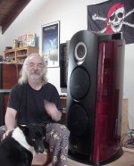
Papa had hernia surgery few years ago ( remember pijama picture , with Pirate flag and Jack) , due to overly enthusiastic big PL amp moving attempt (at least he declared that ) ......... so we don't want him having repeated hernia , this time induced with too much laughing .......

Papa had hernia surgery few years ago ( remember pijama picture , with Pirate flag and Jack) , due to overly enthusiastic big PL amp moving attempt (at least he declared that
) ......... so we don't want him having repeated hernia , this time induced with too much laughing .......Pls show this one of a kind picture. Laughter within reason is best medicine....we must be bloody careful ;
Papa had hernia surgery few years ago ( remember pijama picture , with Pirate flag and Jack) , due to overly enthusiastic big PL amp moving attempt (at least he declared that

just to make this thread even more hysteric and biiig (both of these with my massive contribution ) - speaking of 6.2GB big Pass folder - that's not counting this (he naively left one of his PC's without surveillance ) :
edit: sorry , forgot second , appropriate picture ....
) - speaking of 6.2GB big Pass folder - that's not counting this (he naively left one of his PC's without surveillance ) :edit: sorry , forgot second , appropriate picture ....
Attachments

Last edited:
to tame the BA-3 frontend you could use this variant with feedback....
http://www.diyaudio.com/forums/pass-labs/201281-burning-amp-ba-3b-balanced-35.html#post3175510
but of course you have feedback in the system now.....
Dear gurus [generg, ZM, lhquam, flg, buzzforb,triode_al, and many others]. Please give me guidance regarding this burning question pertaining to the attached file which shows a hypothetical schematic of a burning amp and/or an F6 clone. flg: please note that this front end has voltage gain like you proposed in the 1340 string of posts [wimdehaan circuits].
- Where is a suitable feedback point from the output to the front end?
Thank you, and kind regards.
Attachments
Hi Antoinel,
Please delete me from your list of gurus..... I really cannot answer your question.
I had to simulate it. But I think it might be possible, but a kind of overkill. I made a similar thing combining the best elements of different FW amps, the j-fet input stage from Aleph J, the CCS for the input stage from the BA-1 Frontend and the output part from BA-1. Of course it worked, but was it good? I do not know.
At the moment you are giving up a piece of the simplicity of the FW idea. The BA were thought for more power and demand of course other front ends with higher currents driving the 4-6 pairs...
And the xformers, for instance used in M2 tried to replace the voltage gain normally done by semiconductors by a step up transformer, with some advantages, inter modulation could be lower, and some disadvantages you know.
In your model you are combining a huge amount of semiconductors voltage gain and some gain in the transformer (overload?) and you may loose some driving current for the outputstage ?....the best of three worlds ......? I do not know....
generg: thank you for honest answer. I am glad that you have aready done "mix and match" [or whatever you wish to call your practice] of Pass schematics. Please note that the output stage of the parent BA 3 Front End is a current source generator due to the opposed drains of its output MOSFETs, and absent an intra loop feedback. Thus, the voltage gain of this front end [in its Pass normal operation] is proportional to the value of the load resistor R13 [332 Ohms] in parallel with the high input impedance of the output stage. In the hypothetical schematic name it1035, R13 may be decreased at will to lower the gain to suit the need. This I hope may address your concern above regarding excessive OLG ; which is needed to sacrifice a portion of it anyway to make an amp with a stable closed loop gain of say 26 dB. This is an hypothetical objective.Hi Antoinel,
In your model you are combining a huge amount of semiconductors voltage gain and some gain in the transformer (overload?) and you may loose some driving current for the outputstage ?....the best of three worlds ......? I do not know....
- Home
- Amplifiers
- Pass Labs
- F6 Amplifier