Thanks for the offer.
Probably a better approach for me would be to get 0R20 0.1% resistors and measure the pots with my multimeter.
In trying to duplicate these results with other FETs, different values will be needed because of transconductance variations between the FETs. One or both of the pots are probably useful in the "ultimate" amplifier circuit, and will provide a lot of flexibility to tune the harmonics to one's taste.
lhquam I have a for real wheatstone resistance bridge if you want to send them to me.
Bud
I want to try choke loading my 6v6 pre, got anything that will work. Need 5K and 20mA minimum, with more current capability being better, I assume.
I do not have anything on hand. Will be about 6 weeks at best. I assume this will be directly connected to the plate? If so it needs to be an audio choke, rather than a power choke.
Bud
Thanks for the offer.
Probably a better approach for me would be to get 0R20 0.1% resistors and measure the pots with my multimeter.
In trying to duplicate these results with other FETs, different values will be needed because of transconductance variations between the FETs. One or both of the pots are probably useful in the "ultimate" amplifier circuit, and will provide a lot of flexibility to tune the harmonics to one's taste.
Can't you just measure the total resistance of the paralleled combo then replace the pot/resistor combo with resistors of the same value
Perhaps in the future I will let you guys do all the work.
In the meantime, I will suggest that you have taken it about as far as
it will go, now that you are just down the choices of the Rs values.
I'm at the coast finishing the F6 article up, and no doubt you will be
pleased with yourselves when you see it.

Thank you very much Mister Pass
for this new toy to come! I do not have an ohmmeter that is accurate enough to measure 1/100's ohm. I should purchase some precision resistors to build a Wheatstone bridge.
Can't you just measure the total resistance of the paralleled combo then replace the pot/resistor combo with resistors of the same value
In circuit voltage measurement, and amplify with diff amp?I do not have an ohmmeter that is accurate enough to measure 1/100's ohm. I should purchase some precision resistors to build a Wheatstone bridge.
Last edited:
And the answer is ...
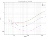
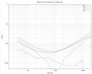
The answer is Rs should be very small. I am using 0R12.
And pots P3 and P4 in post #1844 http://www.diyaudio.com/forums/pass-labs/216616-f6-amplifier-185.html#post3164838 should be adjusted to minimize 2nd harmonic and as far counter-clockwise (wiper toward FET source pin) as possible.
Sounds really good. Here are some plots. (Ignore some plotting artefacts due to a software bug in the harmonic extraction that make the left plot "ratty" between 50 and 200 Hz) The left channel seems to have a lower transconductance JFET, or something the prevents adjusting the THD to levels similar to the right channel.
Attachments
lhquam: I hope that you have the curiosity to forsake Class A operation of Teaser-6 for several days [it is in the bag], and operate it in Class AB mode. Drop the idle bias to 100 mA, and tell us how it sounds by comparison with its established Class A. Noting that the old Classic operated in Class AB and some of its other renditions in Class B, and they sounded great too. This is also an open challenge to Mr. Pass, and Mr. buzzforb and others to move away from this default Class A. Show us that Conceptual F6 sounds great operating in Class AB first, and then its expectedly better sound as Class A. This is a [the] challenge you may wish to face. Afterall, most amplifiers sound their best in Class A!
Not a chance. The amplifier already has rather low open-loop gain. Reducing the bias to 0.1A would drastically reduce the FET transconductance and open-loop gain. Nothing left for feedback to reduce the distortion.
lhquam: I hope that you have the curiosity to forsake Class A operation of Teaser-6 for several days [it is in the bag], and operate it in Class AB mode. Drop the idle bias to 100 mA, and tell us how it sounds by comparison with its established Class A. Noting that the old Classic operated in Class AB and some of its other renditions in Class B, and they sounded great too. This is also an open challenge to Mr. Pass, and Mr. buzzforb and others to move away from this default Class A. Show us that Conceptual F6 sounds great operating in Class AB first, and then its expectedly better sound as Class A. This is a [the] challenge you may wish to face. Afterall, most amplifiers sound their best in Class A!
It runs fine Class-AB, but with the expected deficiencies. Here is Spice simulation with 4 ohm load, 50 watts, 1kHz. THD was 2%.
I have not been closely following this thread. Does the F6 go into class B?
The JLH definitely does not. It does 1.5 x bias, then current clips
What does the F6 do?
Attachments
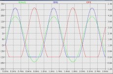
F6 and its clones [Teaser-6, Franken6 etc.] are/seem to be destined to operate predominantly Class A and gracefully beyond it into AB. Open loop gain [OLG] emanates fully from the output stage JFETs. This is unlike the Classic based on BJTs whereby OLG has contributions from the front end and the output stage; with a possible voltage step-down [ OLG control?] by the interstage transformer.It runs fine Class-AB, but with the expected deficiencies. Here is Spice simulation with 4 ohm load, 50 watts, 1kHz. THD was 2%.
Only in Serbia; for your eyes only 007.Pa just posted article
Thank you for responding and your analysis. Teaser-6 conforms to another facet of the Pass Principle; the only source of gain emantes from the least # of gain devices; the output stage JFETs. Please calculate OLG and %THD for 0.13 A bias current and compare with those due to 1.3 A bias you use in Teaser-6. Thank you.Not a chance. The amplifier already has rather low open-loop gain. Reducing the bias to 0.1A would drastically reduce the FET transconductance and open-loop gain. Nothing left for feedback to reduce the distortion.
You should download LTSpice (free) and Do It Yourself, after all, DIYAudio is the name of this collection of forums.
Thank you for responding and your analysis. Teaser-6 conforms to another facet of the Pass Principle; the only source of gain emantes from the least # of gain devices; the output stage JFETs. Please calculate OLG and %THD for 0.13 A bias current and compare with those due to 1.3 A bias you use in Teaser-6. Thank you.
Thank you for your advice. Will do.You should download LTSpice (free) and Do It Yourself, after all, DIYAudio is the name of this collection of forums.
- Home
- Amplifiers
- Pass Labs
- F6 Amplifier