In order for the xfrmr to have a low enough source impeadance to drive the outputs sufficiently, the low source impeadance of the buffer is necessary. The input buffer's output impeadance is "reflected" thru the turns ratio^2 to the output. You could drive the xfrmr directly, if not using FB, but, you would want a very low source impeadance. 
Make it part of a Compound Power Amplifier. Please see the thread in the Pass Labs Forum with the same title. The clone of F6 runs open loop and its output impedance is minimized to that of its mate voltage source amp [VSA] of output impedance <0.1 Ohm; plus other performance goodies. The VSA can be an F5 or your choice. If you operate your F6 clone open loop; will you still need its front end?
The VSA is a feedback amp though ....
And as flg mentioned, yes the input buffers are still needed to allow the tx to be driven by a variety of sources - but as you suggested before, perhaps driving directly by headphone amp might work.
The VSA is a feedback amp though ....
And as flg mentioned, yes the input buffers are still needed to allow the tx to be driven by a variety of sources - but as you suggested before, perhaps driving directly by headphone amp might work.
kasey197. As flg hinted above, keep the front end which also gives other flexibility and also maintains the basic design intact. I am suggesting a transient experiment to tackle your objective. Operate the clone open loop [as a current source amp], and simultaneously lower its output impedance with an independent VSA. In this application, the VSA works like a shock absorber, soaking up excess current from the clone as if it came from the back EMF of the loudspeaker. Clearly, this is wasted [good] current from the clone ; but one gains some and loses something else in return.
N.B. Failed to mention that the VSA is NOT in the/an internal feedback loop of the clone. The clone is operating in free-range mode; and with the low Zo of the VSA to make adaptable to a variety of loudspeakers.
Last edited:
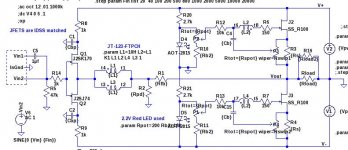
Buzz: You might consider this modification to the circuit. Add 20 ohm pots in parallel to the source resistors. The pot wiper is tied to the capacitors. This provides complete freedom to experiment with balance of top and bottom JFET modulation, and the pot adjustments do not affect the DC bias. Also, the source resistors retain their normal values and WATTAGE.
Below Rs is definitely much cleaner, but it doesn't have same magic as above. Above introduces a bit too much grit, but the overall presentation of space is much more enjoyable. I have some other bad ideas to test and will be back.
Attachments

Don't have Zen pot or any other for that matter. No need, as lowest Rs possible sounds best to my ears. I take it you have not tried it Ilquam. Ill setup my ideas in new thread. Cool thing about F6 is the fact that each half is semi independent, you have great freedom in playing. I will be trying quite a few things over there. I'd interested, come on over. If not, enjoy me talking to myself
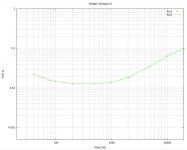
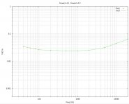
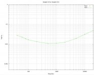
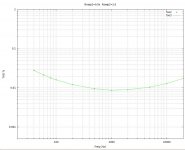
I just ran some measurements of one Teaser-6 channel using a variety of pot adjustments shown below.
we discussed that ( Zen Amount Pot ) few days ago ..... I'm surprised he didn't tried that already , considering that's Buzz in question
hey , Buzz , try one cap above Rs , one bellow ........
that will be nice mix'n'match of harmonics
Attachments
I just ran some measurements of one Teaser-6 channel using a variety of pot adjustments shown below.
Haha told ya

Told me what? Do not forget that high values of Rswip1 and Rswip2 mean higher output impedance and lower damping factor. There is a tradeoff between lower THD and lower Zo. Also consider that small "tweaks" to the relative values of Rswip1 and Rswip2 are comparable to minor adjustments to Rs to correct for transconductance differences of the output FETs and reduce 2nd harmonic.
Haha told ya
Last edited:
Told me what? Do not forget that high values of Rswip1 and Rswip2 mean higher output impedance and lower damping factor. There is a tradeoff between lower THD and lower Zo. Also consider that small "tweaks" to the relative values of Rswip1 and Rswip2 are comparable to minor adjustments to Rs to correct for transconductance differences of the output FETs and reduce 2nd harmonic.
Forget pot and do same thing with different Rs and cap positioning. Both caps don't have to be in same place. All things affect everything and just simmig only goes so far. Listen to cap above on both.( I know you have it that way). Now take upper cap and connect bellow top Rs. Listen and then test not only THD but also harmonic breakdown. Shape the sound man.
You cannot get the 2nd harmonic minimum with just the above/below combos unless you try many many combinations of Rs-above and Rs-below. The variable adjustment greatly simplifies things and does not require readjustment of the DC bias.
Forget pot and do same thing with different Rs and cap positioning. Both caps don't have to be in same place. All things affect everything and just simmig only goes so far. Listen to cap above on both.( I know you have it that way). Now take upper cap and connect bellow top Rs. Listen and then test not only THD but also harmonic breakdown. Shape the sound man.
.... Shape the sound man.

my man Buzz ...... that's good enough for sig
Perhaps my post with the THD vs Freq plots wasn't clear. These were NOT simulations, they were measurements of the actual PCB using the pots.
Forget pot and do same thing with different Rs and cap positioning. Both caps don't have to be in same place. All things affect everything and just simmig only goes so far. Listen to cap above on both.( I know you have it that way). Now take upper cap and connect bellow top Rs. Listen and then test not only THD but also harmonic breakdown. Shape the sound man.
I just ran some measurements....
that was pretty clear
Ilquam,
You are the man. You have put forward a tremendous effort and have offered lots of information that has been helpful, but I am weird. I want to know what you hear.
What differences you perceive, and why you think they are occurring. I am trying to take advantage of your knowledge to help shape my sound, but i cant do that with measurement, solely. I am perhaps asking for the wrong thing(my ignorance again), as I think i want the frequency sweep showing the breakdown of the harmonic structure. Simple version is seen in 3rd pic of this link.
Using FFT spectrum analysers for audio amplifier design
ZM: How much more performance-wise can be squeezed out of the F6 Conceptual Schematic beyond what I am seeing? How will I know when I am getting close?
that was pretty clear
Pa is having fun
zillion of posts ,based on teaser
Perhaps in the future I will let you guys do all the work.
In the meantime, I will suggest that you have taken it about as far as
it will go, now that you are just down the choices of the Rs values.
I'm at the coast finishing the F6 article up, and no doubt you will be
pleased with yourselves when you see it.
I have been watching this whole affair since it started waiting for a working schematic from Mr Pass. And, at the same time being amazed by the talents of this community. I don't have the skills to go from the teaser to working circuits myself but I have tried to follow all the great minds posting their thoughts here. Kudos to all who have elevated a simple audio transformer to the celebrity status of being the centerpiece of over 1800 posts.
While I was waiting I've started collecting parts for an F4 to join my F5. Will I be able to complete it before I'm compelled to collect the parts for an F6?...time will tell.

Attachments

- Home
- Amplifiers
- Pass Labs
- F6 Amplifier