my brain is in red few hour already , alive as Dodo ......... but I'm getting all the time ~1R8 (CL) for output impedance , according to your 4/8R measurement
so , rusty , usually using open/loaded situation for measurement , and too fuzzy to even remember in which bookie to look for this procedure
whatever , after half page of calculus , I keep getting what already calculated just staring at your post
edit:
OL test - we are having same result (43R) , so I'm probably not yet for proper disposal ...... it must be your typo (2R84)
so , rusty , usually using open/loaded situation for measurement , and too fuzzy to even remember in which bookie to look for this procedure
whatever , after half page of calculus , I keep getting what already calculated just staring at your post
edit:
OL test - we are having same result (43R) , so I'm probably not yet for proper disposal
...... it must be your typo (2R84)
Last edited:
Your brain isn't fried, but mine was.  Take one from column A and ...
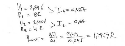
Yes, it should be Rint = 1.8 ohms and damping factor = 4.45 into 8 ohms.
I solve the following equations for Vint and Rint.
Take one from column A and ... Yes, it should be Rint = 1.8 ohms and damping factor = 4.45 into 8 ohms.
I solve the following equations for Vint and Rint.
- (Vint-Vout1)/Rint = Vout1/Rload1
- (Vint-Vout2)/Rint = Vout2/Rload2
- Vint and Rint are the amplifier internal voltage and internal resistance.
- Vout1 and Rload1 are the measured output voltage and output load resistance.
- Vout2 and Rload2 are the measured output voltage and output load resistance.
my brain is in red few hour already , alive as Dodo ......... but I'm getting all the time ~1R8 for output impedance , according to your 4/8R measurement
so , rusty , usually using open/loaded situation for measurement , and too fuzzy to even remember in which bookie to look for this procedure
whatever , after half page of calculus , I keep getting what already calculated just staring at your post
agree with the Rout calcs. The reduction in output impedance is significantly better than implied by the amount of feedback no ? We have reduced gain by 21.6/4.7 = 4.6x
but the output impedance has dropped by 43.3/1.8 = 24x. Maybe just reducing Rs = 0.22 would be enough to get you the desired low output r.... just speculating ....
but the output impedance has dropped by 43.3/1.8 = 24x. Maybe just reducing Rs = 0.22 would be enough to get you the desired low output r.... just speculating ....
Git my new SS output stage finished and operable. Biased great, dead silent with speakers hooked up anear within one inch. Will redo FE tomorrow as well as other side and give a listen. Now i know what Nelson says you gotta give the M2 a second to bias up. Have a couple fiddling options for playing with output. Will report as soon as i can. Be warned, if it sounds goid, you may not hear from me for a while. I always get sucked into listening.
Yeah, Rs = 0R22 should drop Rout to well below 1 ohm. How low is enough?
agree with the Rout calcs. The reduction in output impedance is significantly better than implied by the amount of feedback no ? We have reduced gain by 21.6/4.7 = 4.6x
but the output impedance has dropped by 43.3/1.8 = 24x. Maybe just reducing Rs = 0.22 would be enough to get you the desired low output r.... just speculating ....
All you need is enough to be able to measure the bias current. 0R12 is the smallest I have right now. Simulations give an open-loop gain of about 100 with 0R01, 53 with 0R12, and 41 with 0R22.
Be fearless, drop it to 0.1. It's not like you have a stack of paralleled output devices. In my JLH amp it sounds better with Rs=0.1
I have listened long enough to know that the Teaser-6 will NOT replace either my F5 or F5-balanced.I am starting to have listener fatigue with this amp. Perhaps my implementation isn't up to Papa's standards, but the overall limitations imposed by the "F6 Conceptual Schematic" prevail. Bottom line: Too little open-loop gain.
Sorry to be a wet blanket.
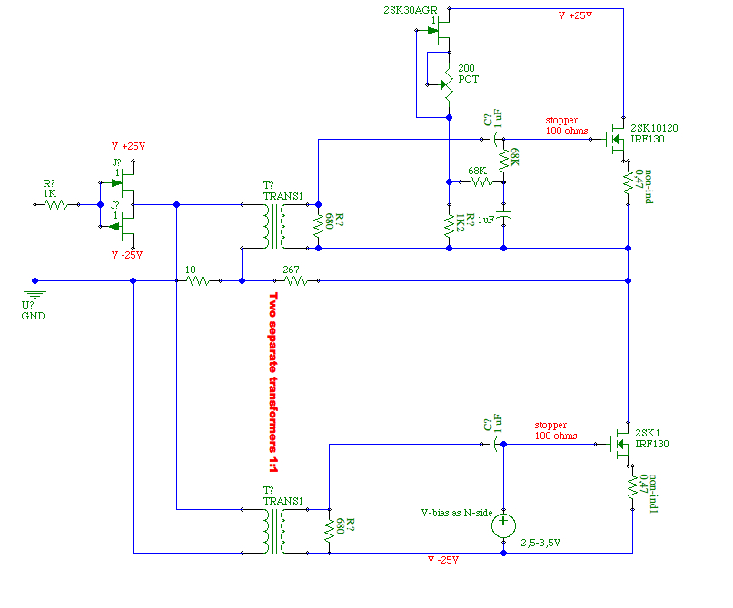
I have voiced some doubts before about the place and type of coupling cap to the gates. imho they could be smaller (what signal do they carry; what resistance do they face after all); now the signal transverses an electrolytic, 220 uF if I am correct.
- I suggested 1uF (10 would be possible too) as my bias is fed by 68k [schema] or 47k [in fact, the first one to be found around].
- whether the cap is on the top side of the transformer as i show or on the bottom: that does not make a difference if I interpret the impedance laws.
Sorry, I myself have not been able to progress much the last weeks
and will not have time for another set of many weeks.
....(what signal do they carry; what resistance do they face after all); ......[/I]
few volts , what else
gates - Pa sez that they're 10K-ish ....... so go figure
There are other ways to lower Zo other than Rs size. We will see which sounds better to my deaf ear. Thanks Stefanoo I have 1K caps currently installed, but will play with that is well. I have never gotten the feeling that Nelson is terribly afraid of Ecaps in his amps and he seems to do OK with his designs. Myriad of choices or alternatives there, so it seems it is best to evaluate before assuming they are a problem. could always use self biased DM devices if it is really a concern. I think he is fancying those types these days anyway. I dont think Ilquam's experience with the amp is a good one to go buy. No slam on hime, as he did a phenominal job with his implementation, but his description is not what i would expect or what I have heard from transformer based designs using PP pentode tubes. That is what yo have here, in a sense. Minus the beautiful glow of course.
I have 1K caps currently installed, but will play with that is well. I have never gotten the feeling that Nelson is terribly afraid of Ecaps in his amps and he seems to do OK with his designs. Myriad of choices or alternatives there, so it seems it is best to evaluate before assuming they are a problem. could always use self biased DM devices if it is really a concern. I think he is fancying those types these days anyway. I dont think Ilquam's experience with the amp is a good one to go buy. No slam on hime, as he did a phenominal job with his implementation, but his description is not what i would expect or what I have heard from transformer based designs using PP pentode tubes. That is what yo have here, in a sense. Minus the beautiful glow of course.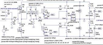
few volts , what else
gates - Pa sez that they're 10K-ish ....... so go figure
aha thats indeed low.
And what about proper loading the outputs; doesn't the spec sheet say 700 ohms or something near? A linear stereo potmeter could help to find the sweetspot.
It is just that I am worried about the 'fatique'. De Fatum.
Thanks Stefanoo
Where is stefanoo?
Nelson loves Elna Silmic. He has stack of them in his B5
Want highest possible open-loop gain? Try this. Rs is only used for measuring bias current, not degeneration.
that's exactly what Buzz is buzzing ,previously mentioning pot across Rs
he's listening now exactly what you drew
Where is stefanoo?
Nelson loves Elna Silmic. He has stack of them in his B5
stay put ;
I'm enough of idiot for this thread

aha thats indeed low.
And what about proper loading the outputs; doesn't the spec sheet say 700 ohms or something near? A linear stereo potmeter could help to find the sweetspot.
It is just that I am worried about the 'fatique'. De Fatum.
that issue is beaten to death in this thread , mostly by me
then Pa came with fact that this Jensen is completely happy as embraced , seeing gate (10K-ish) on one , and low Elna impedance,on other side
of course , proper loading for every xformer still stay as individual case
Want highest possible open-loop gain? Try this. Rs is only used for measuring bias current, not degeneration.
Neat. Flip side to your suggestion. Will it be possible to have only one current sensing resistor [for example 0.1 Ohms]; in series with the drain of the bottom JFET [drain to Out]; or in series with the drain of the upper JFET [drain to V+] ? The LEDs of the bias circuits have a negative temperature coefficient. Maybe glued to the heat sink to maintain a steady idle bias!
- Home
- Amplifiers
- Pass Labs
- F6 Amplifier