.....
However, I can afford to put out this teaser:

code name : TEASER

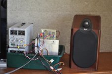
I finally decided to listen the my Guess5 (aka. Teaser) in my normal listening room as shown in the image. I played some selections that previously exhibited defects in other amplifiers.
My next decision is whether to build another prototype board like shown, or to push ahead on the PCB.
- Miles Davis "Sketches of Spain/ Will'O the Wisp: A good test for high frequency problems. Sounds fine.
- Charlie Byrd & Ken Peplowski/ The Bossa Nova Years/Corcovavo: The guitar plucks can exhibit problems in some amps. Sounds fine.
- J. S. Bach/ Toccata and Fugue in D Minor: Pushes the bass - my B&W CDM1 speakers are not up to the task. No problems detected.
My next decision is whether to build another prototype board like shown, or to push ahead on the PCB.
Attachments
I am playing around with higher values source resistors, expecting to settle on something closer to 0R47 instead of 0R12. The LED or zener voltage must increase for higher valued source resistors.No problems, sounds fine. You really got my interest now
The basic rationale is that the local feedback provided by the source resistors is more linear than the global feedback loop in this amplifier. Looking at the 20 kHz signal, there is a 2.5 us phase delay from input to output, which negatively affects the global feedback loop.
I have a fondness for no feedback designs. Try it without any and see if it is stable. Should be able t run the Pspice pretty easy, as you seem to be the bloody master of that program. DF wont be good, but plan to use it on FR with another amp driving woofers.
Has crazy, ridiculous thought today. OPa1632 feeding transformer. Fully differential input stage is definitely overcomplicated
Has crazy, ridiculous thought today. OPa1632 feeding transformer. Fully differential input stage is definitely overcomplicated
I have a fondness for no feedback designs. Try it without any and see if it is stable. Should be able t run the Pspice pretty easy, as you seem to be the bloody master of that program. DF wont be good, but plan to use it on FR with another amp driving woofers.
Has crazy, ridiculous thought today. OPa1632 feeding transformer. Fully differential input stage is definitely overcomplicated
I suspect that there is a "sweet spot" regarding the choice of the source resistor (Rs) and amount of global feedback. I am not sure you really want to run this amplifier totally open-loop. I have calculated open-loop gains at a variety of choices of source resistor:
- Rs=0R47 olg=24
- Rs=0R33 olg=31
- Rs=0R22 olg=41
- Rs=0R12 olg=53
Does olg operation mean a transconductance amp? Please comment on the output impedance, and Gm attendant to the above data for completenessI suspect that there is a "sweet spot" regarding the choice of the source resistor (Rs) and amount of global feedback. I am not sure you really want to run this amplifier totally open-loop. I have calculated open-loop gains at a variety of choices of source resistor:
I need to generate thd vs freq curves for all of these choices of Rs. So far I only have tested the amp with Rs=0R12. Probably a very bad choice in retrospect, because of large global loop delay.
- Rs=0R47 olg=24
- Rs=0R33 olg=31
- Rs=0R22 olg=41
- Rs=0R12 olg=53
In the interim, please listen to the above CDs with past Pass DIY amplifiers you [may] have built for comparison like the underlined.I finally decided to listen the my Guess5 (aka. Teaser) in my normal listening room as shown in the image. I played some selections that previously exhibited defects in other amplifiers.
With mono listening I cannot yet pass judgement on this amplifier. There is no obvious coloration. I did not detect any faults other than a minor power-off click, probably due to the bench supplies.
- Miles Davis "Sketches of Spain/ Will'O the Wisp: A good test for high frequency problems. Sounds fine.
- Charlie Byrd & Ken Peplowski/ The Bossa Nova Years/Corcovavo: The guitar plucks can exhibit problems in some amps. Sounds fine.
- J. S. Bach/ Toccata and Fugue in D Minor: Pushes the bass - my B&W CDM1 speakers are not up to the task. No problems detected.
My next decision is whether to build another prototype board like shown, or to push ahead on the PCB.
Secret Discovered?
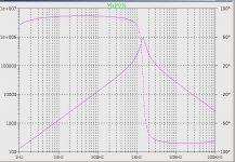
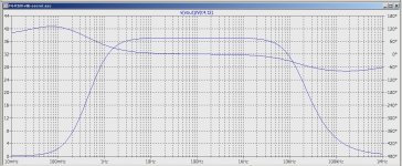
I think I have stumbled onto the secret of the F6. The clue was provided by my investigation of the transformer impedance vs. frequency reported on in post #1213. If that plot is made for the range 1Hz - 100kHz we get the plot shown, where the vertical axis is the impedance across the primary plus the series DC resistance of the primary (point Y to ground).
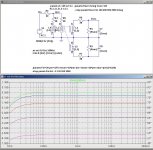
It occurred to me that I should experiment with different values for the impedance of the feedback network. Previously I had only used R1=50 ohms and R2=10 ohms. Today I did Spice simulations for other values of R1 and R2, with R2/R1=5, and found the THD vs. frequency at 1 watt was nearly constant with R1=5K R2=1K. The source resistors were 0R33.
I think I have stumbled onto the secret of the F6. The clue was provided by my investigation of the transformer impedance vs. frequency reported on in post #1213. If that plot is made for the range 1Hz - 100kHz we get the plot shown, where the vertical axis is the impedance across the primary plus the series DC resistance of the primary (point Y to ground).
It occurred to me that I should experiment with different values for the impedance of the feedback network. Previously I had only used R1=50 ohms and R2=10 ohms. Today I did Spice simulations for other values of R1 and R2, with R2/R1=5, and found the THD vs. frequency at 1 watt was nearly constant with R1=5K R2=1K. The source resistors were 0R33.
- 20Hz 0.006625%
- 40Hz 0.004923%
- 100Hz 0.005392%
- 200Hz 0.002859%
- 500Hz 0.005319%
- 800Hz 0.004652%
- 1000Hz 0.004223%
- 2000Hz 0.003027%
- 5000Hz 0.002194%
- 10000Hz 0.003464%
- 20000Hz 0.007607%
Attachments
.I think I have stumbled onto the secret of the F6.
Parastroika! I understood it [back in the 1980s] to mean openess which you are doing.
R2=1k looks very strange.
What signal is left to the primary?
 My stupidity! The THD numbers were correct, but I neglected to notice that the output voltage was being reduced approximately by the ratio of the Z/(Z+R2||R1) where Z is the transformer impedance.
In fact, impedance curves show just the opposite: the input driver impedance should be low in order to flatten the output frequency response curve. In earlier posts, Zen Mod discussed the importance of secondary loading. Here is the transformer V(sec)/Vin vs frequency for different values of Rsec. From bottom to top they are 100R, 200R, 500R, 2K, 1meg. At 100R, the 20 Hz rolloff is only -.18dB vs. -.47dB with an Rsec=1meg. Unfortunately, secondary loading also reduces the open-loop gain.
Attachments
sim/calculate for prototype
then listen and measure
accent on listen
my remarks about importance of secondary loading are staying carved in stone , but if Pa is saying that SS gate impedance is low enough and flat enough for exact Jensen type , I would not argue for a second
especially if I'm not having Jensens on hand
then listen and measure
accent on listen
my remarks about importance of secondary loading are staying carved in stone , but if Pa is saying that SS gate impedance is low enough and flat enough for exact Jensen type , I would not argue for a second
especially if I'm not having Jensens on hand
Last edited:
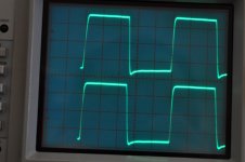
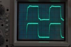
Those Jenson trannies seem to be very good. Here are scope photos of the square wave response.sim/calculate for prototype
then listen and measure
accent on listen
my remarks about importance of secondary loading are staying carved in stone , but if Pa is saying that SS gate impedance is low enough and flat enough for exact Jensen type , I would not argue for a second
especially if I'm not having Jensens on hand
The first image is for a 1MHz square wave from a 50 ohm generator directly into both primaries and no load on the secondaries. The bottom trace is voltage across the primary. The top trace is voltage across the secondary. Horizontal scale is .2us/div.
The second image is for a 100kHz square wave from a 50 ohm generator directly into both primaries and 1nF load on the secondaries (similar to the SS100 JFETs). The bottom trace is voltage across the primary. The top trace is voltage across the secondary. Horizontal scale is 2us/div. There are some artefacts, but I would not call it ringing.
Is that a good transformer?
Attachments
Does anyone know how much DC current through the transformer primary can be tolerated without added distortion? The question is motivated by the issue of the input JFETs not necessarily being well matched in IDSS. A potentiometer could be added to trim the input stage offset voltage at the cost of increasing the impedance driving the transformer.
Here is a plot of open-loop gain vs. frequency. Too much roll-off at high frequencies for a no feedback amplifier.
I have a fondness for no feedback designs. Try it without any and see if it is stable. Should be able t run the Pspice pretty easy, as you seem to be the bloody master of that program. DF wont be good, but plan to use it on FR with another amp driving woofers.
Has crazy, ridiculous thought today. OPa1632 feeding transformer. Fully differential input stage is definitely overcomplicated
Attachments
Is that F5 nein?
Fsechs nein nein -the moderator does not accept that
Last edited:
Does anyone know how much DC current through the transformer primary can be tolerated without added distortion? The question is motivated by the issue of the input JFETs not necessarily being well matched in IDSS. A potentiometer could be added to trim the input stage offset voltage at the cost of increasing the impedance driving the transformer.
do not bother yourself - just make input buffer careful as usual
- Home
- Amplifiers
- Pass Labs
- F6 Amplifier