Does the underlined mean metalized polypropylene? Are you still working with your schematic in post#1023.
MP is here a catch-all for capacitors; MP has good dynamics. Just a contrast to the electrolytic.
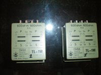
G.- did you received repeaters?
Oh yes ZM, I am now a Repeater.....
I hope it is something like a Terminator....!

Attachments
lhquam,
Q:
- imho the real reason for the effect might be that
- you use a bootstrap for the top bias
- the bias of the top is C4, 44μF connected to the output (and I just note that value differs from C15).
- sonically this is an electrolytic in the signal path!!
- an alternate method would be to connect the bias to the output and insert a big bootstrap in the middle of the R20 (1k4+1k4) (and treat it similar with SAME cap in a split up R21).
if you disconnect the transformer from one of the outputs does it still oscillate/motorboat?
- just for instance the top one gets no modulation, it will be a BA-1 output stage.
I like a method of bias with just a MP cap!
I think I understand the problem with low frequency oscillation. As the frequency gets very low the bypass caps on the input jfet drains become ineffective. What is the impedance of the transformer primary winding as frequencies get very low (<< 1Hz)? The Spice simulation shows the impedance (reactance) of 18 ohms at .7Hz. This means that the jfet input stage will clip at very low frequencies and relatively low signal levels. Of course, with an input cap/resistor RC>.02 secs, such low frequencies will be greatly attenuated before getting to the input stage.
I suggest using 1 watt 15V Zeners to drop the rail voltages to the input JFET drains rather than resistors.
MP is here a catch-all for capacitors; MP has good dynamics. Just a contrast to the electrolytic.
moi witnessed that Pa is one clever chap , using Elna Simics .... all I can do to better it is to put MKC bypass , but same bypass is needed for any other non-audiophool solid cap
Oh yes ZM, I am now a Repeater.....
I hope it is something like a Terminator....!
Generg ....... GET
 ..... Golden Eared Terminator
I think I understand ......... resistors.
in real life you'll have that problem ........ never .
if amp doesn't have motorboating with regular signal , what is possibility to ever have 0.5Hz on input ?
Oh yes ZM, I am now a Repeater.....
I hope it is something like a Terminator....!
I hope you didn't throw packung in trash....... along with small plastic tube.....
I haven't tried a classical (aka. linear) PSU yet. I want current limiting while debugging.Is'nt your motor boating due to PSU?
Haven't you tried a classical one?
No, I think the problem is transformer impedance related.
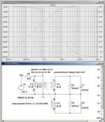
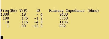
I just performed measurements using a signal generator at .2V p-p output and the schematic shown here. Here are the resulting measurements:
Freq(Hz) Y(V) dB Primary Impedance (Ohms)
1000 .19 -.4 9400
100 .175 -1.2 3760
10 .115 -4.8 1106
1 .03 -16.5 552
Note that the primary impedance calculated includes the DC coil resistance.
Compare the tabulated dB numbers to the Spice Bode plot.
Compare these with
Attachments
Last edited:
I hope you didn't throw packung in trash....... along with small plastic tube.....
Oh man, I nearly did......
thank you very much much much for the known parts!

and for the unknown I must look what they are...rest in PM
...
in real life you'll have that problem ........ never .
if amp doesn't have motorboating with regular signal , what is possibility to ever have 0.5Hz on input ?
Is it possible on power-on, if there is a power fluctuation, or if the input is unplugged or replugged?
Is it possible on power-on, if there is a power fluctuation, or if the input is unplugged or replugged?
with those RC constants in bias nets , not possible in powering on
for plugging-unplugging - it's not easy to make fool-proof amp , and it's certainly impossible to make it idiot-proof ;
I was repairing one channel/section of radio mixing console - live , during airing,I was frequently plugging/unplugging XLR's ......... but only when I was in idiot-mode , I made the same with RCA's ........
but I think it's not problem even with that
You are probably right. I think with the larger caps suggested by Nelson the problem will be eliminated or at least minimized, particularly if the input is frequency limited to above a few Hz.with those RC constants in bias nets , not possible in powering on
for plugging-unplugging - it's not easy to make fool-proof amp , and it's certainly impossible to make it idiot-proof ;
I was repairing one channel/section of radio mixing console - live , during airing,I was frequently plugging/unplugging XLR's ......... but only when I was in idiot-mode , I made the same with RCA's ........
but I think it's not problem even with that
I got worried when my build with 22uf caps and 20k resistors occasionally got into an oscillation. I first encountered it when running low frequency square wave response tests. I later discovered that relatively low levels of <1Hz sine wave signals would do it.
I haven't tried a classical (aka. linear) PSU yet. I want current limiting while debugging.
No, I think the problem is transformer impedance related.
I just performed measurements using a signal generator at .2V p-p output and the schematic shown here. Here are the resulting measurements:
Freq(Hz) Y(V) dB Primary Impedance (Ohms)
1000 .19 -.4 9400
100 .175 -1.2 3760
10 .115 -4.8 1106
1 .03 -16.5 552
Note that the primary impedance calculated includes the DC coil resistance.
Compare the tabulated dB numbers to the Spice Bode plot.
Compare these with
Sorry, i am not able to read this.
I just remember of one culprit PSU producing motorboating.
Some pumping due to current limiting?
Forgive to insist.
Sorry about the table in the previous post. I couldn't figure out how to get white space characters to be retained. Here is the table as an image, and an update of the schematic to include the coil DC resistances.Sorry, i am not able to read this.
I just remember of one culprit PSU producing motorboating.
Some pumping due to current limiting?
Forgive to insist.
Attachments
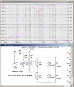
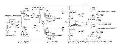
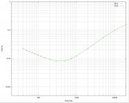
And hopefully it does not motorboat or sing. Will you listen to this clone of F6? Best regardsHere is the update schematic and THD vs Frequency plot
Last edited:
I listened to this single channel in my workshop, a room which is not nearly as lively at my normal listening room. My first impression was that the high end was missing, but this is mostly due to the differences in room acoustics. I measured the hi freq rolloff. 20kHz -.446dB, 40kHz -1.4dB.And hopefully it does not motorboat or sing. Will you listen to this clone of F6? Best regards
I plan to build a second channel and use both with an F5 power supply that is currently unused. Then I can do some serious listening.
half a db on 20k is nothing to write home about
you can try to tighten freq. extremes with little extra loading on secs (resistor in parallel) but , from my experience with decent repeaters - not necessary if you are already there .
vividness is what we are looking for ,when introducing xformers in chain
.... and happily ever after .....

you can try to tighten freq. extremes with little extra loading on secs (resistor in parallel) but , from my experience with decent repeaters - not necessary if you are already there .
vividness is what we are looking for ,when introducing xformers in chain
.... and happily ever after .....
I welcome suggested changes to the F6 circuit shown in post #1214. I plan to send off PCB design files for fabrication soon and would like to avoid having to make major changes to resulting boards.
BTW: I have been thinking about making boards that conform to the "Universal Mounting Spec" {UMS), but I have a couple of reservations.
BTW: I have been thinking about making boards that conform to the "Universal Mounting Spec" {UMS), but I have a couple of reservations.
- I currently use ExpressPCB for fabrication. They provide a very nice board layout editor, fast turn-around times, and good prices, particularly for 2.5"x3.8" prototype boards. The UMS boards would approximately double to costs for prototypes. Can someone suggest another vendor that would be less expensive for prototyping the larger boards? The F6 will nicely fit on the 2.5"x3.8" board, but it does not conform to the UMS.
- I suggest an extension to the UMS for power and I/O connections. I find that hex standoffs are extremely convenient for DIY projects and allow assembly/disassembly of boards to heatsinks without soldering and unsoldering. I adopted the practice from the FX5 layout: thanks EUVL. Similarly, gold-plated .1 inch spacing headers are nice for input connections to the board. Boards can be swapped out and in in just a few minutes with such connections.
Last edited:
I welcome suggested changes to the F6 circuit shown in post #1214. I plan to send off PCB design files for fabrication soon and would like to avoid having to make major changes to resulting boards.
BTW: I have been thinking about making boards that conform to the "Universal Mounting Spec" {UMS), but I have a couple of reservations.
- I currently use ExpressPCB for fabrication. They provide a very nice board layout editor, fast turn-around times, and good prices, particularly for 2.5"x3.8" prototype boards. The UMS boards would approximately double to costs for prototypes. Can someone suggest another vendor that would be less expensive for prototyping the larger boards? The F6 will nicely fit on the 2.5"x3.8" board, but it does not conform to the UMS.
- I suggest an extension to the UMS for power and I/O connections. I find that hex standoffs are extremely convenient for DIY projects and allow assembly/disassembly of boards to heatsinks without soldering and unsoldering. I adopted the practice from the FX5 layout: thanks EUVL. Similarly, gold-plated .1 inch spacing headers are nice for input connections to the board. Boards can be swapped out and in in just a few minutes with such connections.
I would be interested in joining you in a pair of boards. I have some old ADC transformers that would mount off the board and have the SemiSouth already. I will split the cost down the middle or however you would like.
Rush
Rush and lhquam. Would you say that you now have a functioning clone of F6 which is relatively 90% [or better] developed?I would be interested in joining you in a pair of boards. I have some old ADC transformers that would mount off the board and have the SemiSouth already. I will split the cost down the middle or however you would like.
Rush
- Home
- Amplifiers
- Pass Labs
- F6 Amplifier