Anyone have an opinion of the Vishay Roederstein Metallized Polypropylene Film Capacitor (MKP)?
It's bigger.
........
I just hook these things up and see what I get.

me too , but we are splittin' da hair here ........

you know better than moi that good ones will work good , doesn't matter how hooked they are.....but less than good ones will work good only in ideal conditions
......but less than good ones will work good only in ideal conditions
and they'll work no better than just good
and they'll work no better than just good
I can do this 'till forever
Are your saying they will work good or better than OK?
You two are funny!
Burning up a bunch of space someone will have to dig through looking for quality information.
Oops, I just posted and provided no quality info again! Doh!
A little DC won't kill the performance, just limit the bandwidth. Effects bass by saturating the core.
Hope I saved the post,
Rush
LOL
naah
sometimes even I can't keep with my self
what I meant is simple - when you achieve adequate working conditions for xformer - great one will work great , good ones will work good
but , when you have less than optimal setup , great ones will work good , while good ones will work mediocre
so - conclusion is simple - you need to put some (real ) time to achieve best workaround for xformer , where Spice can't help you much .
it's simple if you have enough mileage , and not so if you don't
for instance , I had opportunity to be advised that xformer can't be used for differential I/V conversion with two PCM1704 , especially with primary connected just to chips outputs ; luckily , I was enough ignorant to not obey local experts , invest some time in following my ignorant instincts ..... testing at least 15 different xformers ....
as Pa wrote - I just hook these things up and see what I get.
Last edited:
Compound Power Amplifiers
The Title [Compound Power Amplifiers] is an outgrowth of the intellectual stimulation and inspiration embodied in the F6 Amplifier thread. I started its own thread of the same title so as to keep the F6 Amplifier thread solely dedicated to it. DIYers have simulated, surmised, reflected, speculated, analysed, peacefully argued and chatted about simplified F6. Lucky Mr. Pass, he is already listening to an F6 [see What's New on www.firstwatt.com]. I show in the first post of the thread "Compound Power Amplifiers" a possible working model for simplified F6. It can be assembled, tweaked, auditioned and critiqued in a matter of hours.
The Title [Compound Power Amplifiers] is an outgrowth of the intellectual stimulation and inspiration embodied in the F6 Amplifier thread. I started its own thread of the same title so as to keep the F6 Amplifier thread solely dedicated to it. DIYers have simulated, surmised, reflected, speculated, analysed, peacefully argued and chatted about simplified F6. Lucky Mr. Pass, he is already listening to an F6 [see What's New on www.firstwatt.com]. I show in the first post of the thread "Compound Power Amplifiers" a possible working model for simplified F6. It can be assembled, tweaked, auditioned and critiqued in a matter of hours.
me too , but we are splittin' da hair here ........
you mean you're serving ragout of bunny?
what you mean with parasitic currents ?
loading of secondary is of most importance here
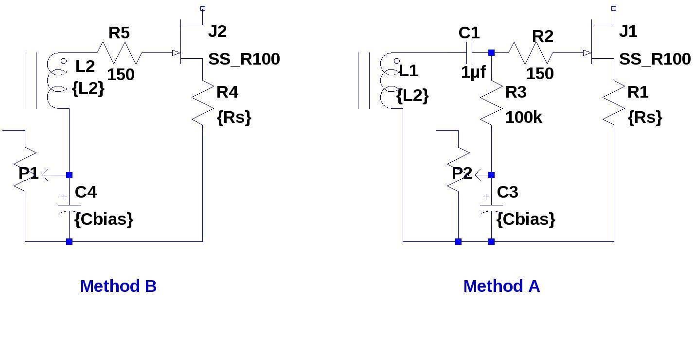
Referring back to post 742 http://www.diyaudio.com/forums/pass-labs/216616-f6-amplifier-75.html#post3124507, is there any problem using method B if an appropriate load resistor is placed across the secondary? As discussed earlier, method B might suffer more from xformer parasitic currents, but has fewer capacitors involved.
looking at pic from #742 (attached )
in case B AC path for modulation is through C4 , which serve also as bias voltage blocking/maintaining/smoothing cap
in case A AC path for modulation is through C1 ; in that case C3 is just bias voltage blocking/maintaining/smoothing cap
in case B AC path for modulation is through C4 , which serve also as bias voltage blocking/maintaining/smoothing cap
in case A AC path for modulation is through C1 ; in that case C3 is just bias voltage blocking/maintaining/smoothing cap
looking at pic from #742 (attached )
in case B AC path for modulation is through C4 , which serve also as bias voltage blocking/maintaining/smoothing cap
in case A AC path for modulation is through C1 ; in that case C3 is just bias voltage blocking/maintaining/smoothing cap
Can C4 serve both duties as well as C1/C3 in method A?
Can C4 serve both duties as well as C1/C3 in method A?
it is not an issue
fact is that in both cases we are having one cap in series with secondary
and in case A it's possible to have adequate loading of secondary
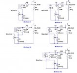
In the following drawing, methods B1, A1, and A2 show some alternatives for loading secondary winding and biasing the output FET. In all cases, Rsec is the secondary load resistance.
if you ask me - any of A derivatives
which one suits you most ......
if you ask me - any of A derivatives
which one suits you most ......
I don't like caps in the signal path. They make me want to buy $100 each or more caps and worry why I was too cheap to buy Audionote $1000 silver foil caps. So my 1st preference is "B".
Then it occurred to me that sometimes we do things that make the output device exhale the smoke within. Does this trick of letting the smoke out ever short the gate to a rail and possibly burn out a winding on the secondary?
That would be bad, making me reconsider "A". But I don't know the likely hood of that. I have not let the smoke out yet.

Rush
I told ya - in B you have cap in AC path , too
think about impedances
Yes, but, the cap is on the non-signal side of the winding where the AC goes to ground (or rail) with a lot of impedance between, so I think the cap is less critical than halving the full signal coupling through a cap.
I could be wrong, but that is what I think right now,
Rush
there is no non-signal side
even in case of B1 case (post #774) , where you have proper loading resistor across secondary , value of C2 must be sized accordingly to wiper-lower end section of trimpot , calculated as bypass cap , or it will not serve prescribed duty
in that case - it's AC impedance is low , so trimpot value is of no importance , AC wise
conclusion - cap is in AC signal path ...... as it must be , because Jfet likes to see signal between S and G
- Home
- Amplifiers
- Pass Labs
- F6 Amplifier