Norton Security Suite did not allow me to complete the above. A potential virus problem. Still, please comment on Figure 2 as it relates to the writing of Mr. Pass. Both of the TCAs in Fig 2 are working in the common source or opposed drains configuration. Will Figure 2 work as a klone [ZM's word useage] to the output stage of simplified F6; theoretically speaking.
It's a little tough to make fig 2 work - both those parts are N channel in
the drawing. I have never had much luck running N channel parts with the
Source attached to V+.
Presumably he meant to have P channel devices on the top. If you can get
good symmetry between P and N channel parts, you're all set.

the drawing. I have never had much luck running N channel parts with the
Source attached to V+.
Presumably he meant to have P channel devices on the top. If you can get
good symmetry between P and N channel parts, you're all set.

are you boyz talking about part from Self's book ?
this (page 395 etc.):
with this pics (attached )
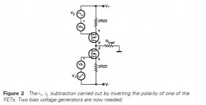
it seems there is a mistake in upper mosfet symbol (polarity)
( as always , I'm doing all the hard work with text and graphics ......... )
)
this (page 395 etc.):
No doubt something could be done with industrial-sized current-mirrors,
but it struck me that the circuit could be rearranged as Figure 2, by making
use of complementary devices. We now need two bias voltages Vb1, Vb2,
and the positioning of the two signal sources V1, V2 on opposite rails looks a little awkward, but at least the current-difference will be mathematically
perfect, if Kirchhoff has anything to say on the matter.
So far so good. We now have a single current output iout. But is this
any use for driving loudspeakers? I am assuming that current-drive of
speakers is not the final goal; I appreciate that this can be made to work,
and promises some tempting advantages in terms of reducing bass-unit
distortion.4 My immediate reaction to Figure 2 was no, it can’t work,
because with a high impedance output, the output stage gain will vary wildly
with load impedance making the amount of NFB applied a highly variable
quantity. It would also appear that any capacitive loading of this high-
impedance node would generate an immediate output pole that would
make stable compensation a waking nightmare.
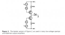
However, just as I was discarding the notion, it occurred to me that the
structure in Figure 2 looks very much like the bipolar common emitter
(CE) stage in Figure 3. This is widely used in low voltage opamps because
the low saturation voltage allows a close approach to the rails.5 The more
usual emitter follower type of opamp output is usually called a CC or common-collector stage. It is highly probable that the widest application
of these voltage-efficient CE configurations is in the headphone amplifiers
of personal stereos.
At about the same time I encountered a paper by Cherry6 which pointed
out that, so long as NFB is applied, the output impedance of such a stage
can be as low as for the usual voltage follower type output. Cherry’s paper is
dauntingly mathematical, so I will summarise it thus. The vital point about
using NFB to reduce the output impedance of an amplifier is that the
amount of NFB applied must be calculated assuming that the open-loop case
is unloaded. This condition looks unfamiliar, because the average ampli-
fier usually has a fairly low output resistance even when open-loop, due
to its output follower configuration, and so the loaded/unloaded distinc-
tion makes only a negligible difference when calculating the reduction of
output resistance by NFB.
Using this condition, Cherry shows that output impedance of a CE stage
should be exactly equivalent to the usual CC stage, when the global NFB is
applied. I appreciate that this result is counter-intuitive; it looks as though
the current output version must have a higher output impedance, even
with NFB, but it appears not to be so. Doubters who are unafraid of matrix
algebra should consult Cherry’s paper.
with this pics (attached )
it seems there is a mistake in upper mosfet symbol (polarity)
( as always , I'm doing all the hard work with text and graphics .........
)Attachments
.......I have never had much luck running N channel parts with the Source attached to V+......
Attachments

It's a little tough to make fig 2 work - both those parts are N channel in
the drawing. I have never had much luck running N channel parts with the
Source attached to V+.
Presumably he meant to have P channel devices on the top. If you can get
good symmetry between P and N channel parts, you're all set.
Thank you for taking the time to respond.
Fortunately, I did not mean or imply to use the bolded statement above. These are the 2 exact questions which pertain to Figure 2 of OTLAmp5 several threads earlier.
- Suppose each of the TCAs is a dual polarity version of ACA#1. Will the circuit work?
- Suppose the output stage of each TCA is the opposed collectors of matched and complementary symmetry BJTs. I have two stereo TCAs which fit this specific description. Thus, I am able to answer the question; will this BJT circuit work and how well will it perform?
consider one basic amp as Black Box
as long you're using identical Black Boxes , you can bridge them , parallel them , bridge again , parallel again
(amp) cell doesn't know how crazy load on output is
all you need to know is that with each bridging output impedance of combo is double , comparing to cell output impedance ..... but that's pretty irrelevant in case of TCA
how well it would work ........ good if cell is working good
consider one basic amp as Black Box
as long you're using identical Black Boxes [for example two identical ACA#1 - like devices; each of which has its own independent dual polarity power supply], you can bridge them [normally acceptable for TCAs; but less so for VSAs without adding power resistors in series with their outputs] , parallel them , bridge again , parallel again
(amp) cell doesn't know how crazy load on output is
all you need to know is that with each bridging output impedance of combo is double , comparing to cell output impedance ..... but that's pretty irrelevant in case of TCA
how well it would work [this is the meat of my question in the previous thread] ........ good if cell is working good [ for example; like ACA#1 and other Pass amps like it] /QUOTE]
Great explanation ZM. Thank you.
If a dual polarity output stage with uber low distortion is desired, it seems the no longer made, Toshiba power fets, with true complimentary characteristics, would be desirable.
I was sloppy in using the underlined in an earlier thread. I meant to say a dual polarity power supply for each of the ACA#1 [and for other Pass amps of similar topology].
I am glad my mistake inadvertently gave you the new option for the output stage you wrote about.
as long you're using identical Black Boxes , you can bridge them , parallel them , bridge again , parallel again(amp) cell doesn't know how crazy load on output is
except that when you bridge a Class AB amp, you halve the impedance of the load and the heat necessary to be dissipated doubles.
Of course, we're not AB'ing here...
series resistor on output is desirable in case of parallel connection of black boxes , not bridging , which is (of course) series arrangement
that doesn't have any connection with nature of amp - be it voltage or current source
ZM: Figure 1 of OTLAmp5 shows two ACA#1s connected in a bridge configuration. I believe we all agree that it works for whatever value it embodies.
Figure 2 of OTLAmp5 shows two TCAs [each having its independent dual polarity power supply] which are not connected in the bridge configuration like in Figure 1. In my mind, the operation of the upper TCA is like the operation of the upper JFET in the simplified F6 schematic. Ditto for the operation of the lower TCA which I liken to that of the lower JFET in the simplified F6 schematic.
I do not believe this following QUESTION was answered in a straightforward and concise manner. Is each TCA in Figure 2 of OTLAmp5 operating like its corresponding JFET in the simplified F6 schematic?
ZM: .........
Figure 2 of OTLAmp5 shows two TCAs [each having its independent dual polarity power supply] which are not connected in the bridge configuration like in Figure 1. In my mind, the operation of the upper TCA is like the operation of the upper JFET in the simplified F6 schematic. Ditto for the operation of the lower TCA which I liken to that of the lower JFET in the simplified F6 schematic.
........
you'll have zilch on output
- Home
- Amplifiers
- Pass Labs
- F6 Amplifier