why not ?
😉
see ; +/-20V arbitrary - written for then actual chat
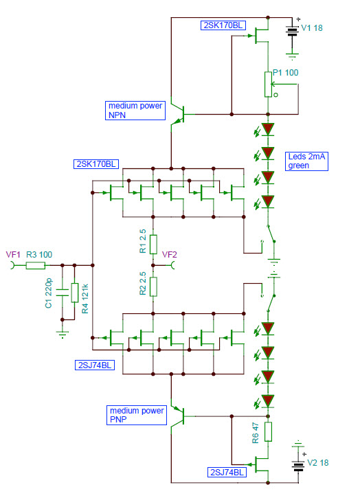
later I saw interesting idea too - called Hawksford buffer (second pic )
plain one is cascode voltage biass referenced to gnd , H. same referenced to sources - having as result that jfets are working in real constant voltage mode
search to read what's difference - lower output impedance , if I remember that well
didn't measured , didn't tried
The Hawksford circuit is what I am going to have driving the FE of my F6 and I have some questions. First concerns the Vref for the BJT. Based on history and whats out there, I was thinking that 5-6 LED's would be better, as this would put the Jfets in the 10V range that they seem to like. It would also allow them to be run at full Idss with no worries. Second; in Joachim's layout, he has a switch at the ground point of the LED's and Jfet sources. Is this meant to be a relay initiated thing? Third, based on Nelson and others comments, if matched Jfets were used, the source resistors could be dropped, correct. I have a place in the pcb to add an offset pot as a safety margin, but would like to go without it.
Edit: Great thing about the circuit is the fact that it can be built as per the original schematic with jumpers and then added to, testing along the way, and checking for improvements in either measurement or sound.
Attachments

Last edited:
Its there in the original post now. Did it while you were making fun of me😀
The Hawksford circuit is what I am going to have driving the FE of my F6 and I have some questions. First concerns the Vref for the BJT. Based on history and whats out there, I was thinking that 5-6 LED's would be better, as this would put the Jfets in the 10V range that they seem to like. It would also allow them to be run at full Idss with no worries........
shortly - yes
.... Second; in Joachim's layout, he has a switch at the ground point of the LED's and Jfet sources. Is this meant to be a relay initiated thing? ....
jumpers, switch , or whatever - make it one or another way ...... but make it switchable between both ways , to hear what's your bloody preference

......Third, based on Nelson and others comments, if matched Jfets were used, the source resistors could be dropped, correct. I have a place in the pcb to add an offset pot as a safety margin, but would like to go without it.
.......
10R trimpot can't do any harm ; you can easily toss it out
........
Edit: Great thing about the circuit is the fact that it can be built as per the original schematic with jumpers and then added to, testing along the way, and checking for improvements in either measurement or sound.

This will oscillate as presented - try putting some Gate stoppers on the Jfets.
Of course with a small amount of Source resistance on each, say 10 ohms,
and a lower supply voltage you can dump the cascoding altogether.
😎
Can you say Beast With a Thousand Jfets?
Of course with a small amount of Source resistance on each, say 10 ohms,
and a lower supply voltage you can dump the cascoding altogether.
😎
Can you say Beast With a Thousand Jfets?
ZM and buzzforb: Please clarify.
- Is the primary winding of transformer driven in a differential manner by the dangling connections off the source pins?
- Is feedback going directly to the junction VF2 in the above schematic. If yes, won't it be positive feedback which may oscillate the power amp?
.....
Can you say Beast With a Thousand Jfets?
ZM and buzzforb: Please clarify.
- Is the primary winding of transformer driven in a differential manner by the dangling connections off the source pins?
- Is feedback going directly to the junction VF2 in the above schematic. If yes, won't it be positive feedback which may oscillate the power amp?
naah
that's buffer as you already know it , with output from VF2 node
dangling sources are one connection for LED cascode reference ; second one is ground
follow link where buzz quote Mighty Moi - you'll find all info you need
This will oscillate as presented - try putting some Gate stoppers on the Jfets.
Of course with a small amount of Source resistance on each, say 10 ohms,
and a lower supply voltage you can dump the cascoding altogether.
😎
Can you say Beast With a Thousand Jfets?
Just used the schematic posted and have added the gate stoppers on PCB. As far as the cascode and Rs, i might as well add it to the pcb. Jumpers, jumpers everywhere. I probably should take Nelson's hint and drop the cascode...but what does he know😀
Edit:
I assumed the cascode would help with considerable Ciss of mulitple input pairs, even operated as source follower. Is this not a concern in terns of bandwidth?
EDIT:EDIT:
If nothing else, it will serve as propoer storage place for future FE parts for other amps.😀
Last edited:
I panicked; fearing that buzzforb's amp may buzz and burn up!
naah
that's buffer as you already know it , with output from VF2 node
dangling sources are one connection for LED cascode reference ; second one is ground
follow link where buzz quote Mighty Moi - you'll find all info you need
Teaser-6 "tweakable" parameters
The "F6 Concept Schematic" and the LHQUAM Teaser-6 schematic create an amplifier containing some parameters that can be "tweaked". This note discusses those parameters and their implications for the resulting sound of the amplifier.
To limit the parameter set, I will start by assuming a single pair of output FETs and a target output of 25 watts into a nominal 8 ohm speaker. This implies roughly 24 volt rails and 1.3 amp idle current for class A operation. However, the following discussion doesn't really depend on the top level choise of wattage and number of FET pairs.
The remaining parameters that might affect the sonic signature of the amplifier are:
Feedback network resistors R2, R1, where R1 is from output to feedback node and R2 is from feedback node to ground.
Output FET source degeneration resistors Rs.
There are not really any other "tweakable parameters", unless some other components are added to the schematic.
See the image below for the effects cause by changes to these parameters. (Can someone tell me how to get a table into the body of the a post without using attachments? White space formatting gets removed, screwing up the columns).
This amplifier is very different from the F5 because of the transformer. The transformer adds a phase delay of about 2.5us. Thus, global feedback will likely have a different sonic signature vs. local feedback, or no feedback.
EXPERIMENT WITH A VARIETY OF PARAMETER VALUES:
The source degeneration resistors Rs can be different for the upper and lower FETs. Small differences might be used to null the 2nd harmonic at a particular frequency. Large differences can be used to deliberately increase the 2nd harmonics.
As you can see, there are a relatively small number of adjustable parameters that can change the sonic signature of the F6. I suggest setting R1=50R and using a 2 watt, 10R or 20R potentiometer for R2 to "tweak" the closed-loop gain. My Teaser-6 PCB has provisions for a .1" spacing terminal block for the source resistors, enabling easy experimentation with different values of the source resistors.
Attachments

Last edited:
and you can modulate them from bottom of Rs ....... or from top of Rs ....... or one from bottom and other from top ....... or the other way around .........
Interesting. Do you have any subjective experience with those combinations?and you can modulate them from bottom of Rs ....... or from top of Rs ....... or one from bottom and other from top ....... or the other way around .........
lhquam: I am glad you are connecting the subjective "sonic signature" of the amp to its objective and measureable parameters. So, your reference loudspeaker will sing with a different voice which is discernible to you with each substantial [and maybe not] tweak. Clearly one "sweet" voice [to your hearing] will eventually stand out and be adopted.The "F6 Concept Schematic" and the LHQUAM Teaser-6 schematic create an amplifier containing some parameters that can be "tweaked". This note discusses those parameters and their implications for the resulting sound of the amplifier.
The remaining parameters that might affect the sonic signature of the amplifier are:
This amplifier is very different from the F5 because of the transformer. The transformer adds a phase delay of about 2.5us. Thus, global feedback will likely have a different sonic signature vs. local feedback, or no feedback.
.
Please reconfirm in your table of parameters the following. Will increasing Rs increase or decrease damping factor? Thank you.
- Home
- Amplifiers
- Pass Labs
- F6 Amplifier