As you can imagine, there are different qualities of transformer just like any other component, and this is significant for a class A amplifier - if using a cheaper version, even from say RS, Element 14, etc, increase the size to 500VA or as James mentioned, 2 X 300va and go 'mono-block'
Also, don't 'skimp' on the quality of the capacitors - the amount of uF isn't the only determining factor and unfortunately, good quality capacitors cost more, but a good investment for an amp of this quality.
James said, 2 X 300 VA transformers
Also, don't 'skimp' on the quality of the capacitors - the amount of uF isn't the only determining factor and unfortunately, good quality capacitors cost more, but a good investment for an amp of this quality.
James said, 2 X 300 VA transformers
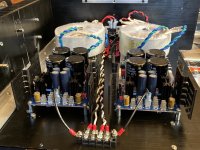
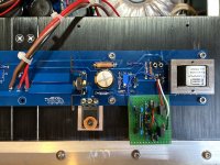
For going dual-mono, the practice I've adopted is to keep the PSUs completely separate for each channel. The only thing the two channels share is the AC power cord, even the power fuses are separate. The first picture shows what I did for my F6. I have a similar arrangement in my Aleph J. Each PSU board has a separate chassis gnd connection, which is through a CL-60 thermistor on the board. The audio grounds are maintained as separate star grounds for each channel. A short wire is routed from the star ground node on the PSU to the speaker (–) terminal. A separate ground wire connects the PSU to the channel board.
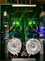
The second picture shows the overall PSU and speaker wiring. I don't find it necessary to twist channel board power connections, I simply route them closely to each other and secure with cable ties.
The second picture shows the overall PSU and speaker wiring. I don't find it necessary to twist channel board power connections, I simply route them closely to each other and secure with cable ties.
Attachments
Last edited:
do you put a CL-60 on each PS ground to chassis? .
Yes
Thanks for the transformer info.
Regarding PSU caps I was thinking high relatability series 35V Nichicon 22,000uF units (using the DIYAudioStore PCB)
LGU1V223MELC Nichicon | Capacitors | DigiKey
Can’t seem to find much better that are readily available...
Regarding PSU caps I was thinking high relatability series 35V Nichicon 22,000uF units (using the DIYAudioStore PCB)
LGU1V223MELC Nichicon | Capacitors | DigiKey
Can’t seem to find much better that are readily available...
Following up with some measurements of my recently completed F6...
Hooking up my 339A to the amp revealed quite a bit more H2 than I was anticipating. At my customary output level of 5 Watts, there was about 1.2% THD, predominately 2nd harmonic (H2), with a noticeable amount of 3rd as well. At 1 Watt output, THD was about 0.8%, almost entirely H2. Since I started with a modification to the connection of C1, I decided to reverse that mod in order to re-measure a baseline with the bias coupling capacitors (C1 & C2) in their default configurations, meaning low side connected to the Source of their corresponding Mosfets.
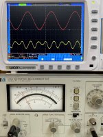
While I had the amp opened up, I also took the opportunity to increase the bias current to 1.64 Amps. The newer configuration has now been through a few listening sessions and an overnight thermal soak. The picture shows the latest measurement at 5 Watts output. Distortion is now down to 0.07% with a mix of H2 and other harmonics. This is a lower level of THD than my Aleph J exhibits at the same power output, though the Aleph J presents almost all H2. Of somewhat academic interest, at 1 Watt output, the F6 has a measured THD of 0.025%, with a residual waveform that looks much like it does at 5W output.
Subjectively, the amp sounds wonderful. It needs a longer warm up period before the heat sinks reach thermal equilibrium. Once that has happened, the instrumental detail of recordings is almost uncanny, as is the spatial detail (how ever that happened to be engineered in the recording studio). The difference in sound, compared to the the previous configuration with its higher THD, is difficult to describe. The high level of (negative) H2 present may have sounded more exciting on some recording, but would have likely resulting in more listening fatigue. As with the Aleph J, I expect the sound of the amp to evolve a bit further as it gets more playing time.
I do have another measurement to make to see how the Diamond buffer front end is doing its job. Later on, I may try goosing the bias current up to 1.8 Amps to see how that sounds. I think that's about as hot as I will want to run the amp. The big aluminum L brackets that I added are definitely doing their job, as the base plate of the amp gets pretty warm along with the main heat sinks.
Hooking up my 339A to the amp revealed quite a bit more H2 than I was anticipating. At my customary output level of 5 Watts, there was about 1.2% THD, predominately 2nd harmonic (H2), with a noticeable amount of 3rd as well. At 1 Watt output, THD was about 0.8%, almost entirely H2. Since I started with a modification to the connection of C1, I decided to reverse that mod in order to re-measure a baseline with the bias coupling capacitors (C1 & C2) in their default configurations, meaning low side connected to the Source of their corresponding Mosfets.
While I had the amp opened up, I also took the opportunity to increase the bias current to 1.64 Amps. The newer configuration has now been through a few listening sessions and an overnight thermal soak. The picture shows the latest measurement at 5 Watts output. Distortion is now down to 0.07% with a mix of H2 and other harmonics. This is a lower level of THD than my Aleph J exhibits at the same power output, though the Aleph J presents almost all H2. Of somewhat academic interest, at 1 Watt output, the F6 has a measured THD of 0.025%, with a residual waveform that looks much like it does at 5W output.
Subjectively, the amp sounds wonderful. It needs a longer warm up period before the heat sinks reach thermal equilibrium. Once that has happened, the instrumental detail of recordings is almost uncanny, as is the spatial detail (how ever that happened to be engineered in the recording studio). The difference in sound, compared to the the previous configuration with its higher THD, is difficult to describe. The high level of (negative) H2 present may have sounded more exciting on some recording, but would have likely resulting in more listening fatigue. As with the Aleph J, I expect the sound of the amp to evolve a bit further as it gets more playing time.
I do have another measurement to make to see how the Diamond buffer front end is doing its job. Later on, I may try goosing the bias current up to 1.8 Amps to see how that sounds. I think that's about as hot as I will want to run the amp. The big aluminum L brackets that I added are definitely doing their job, as the base plate of the amp gets pretty warm along with the main heat sinks.
Attachments
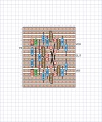
Following a few sets of measurements and some conversation with Mark Johnson, who is responsible for the Austin input stage, I've determined that the diamond buffers I'm using in my F6 are doing their job quite well. It turns out that passing square waves from my iPad through some inexpensive mini-phono to RCA cables caused a small amount of ringing right at the input of the amp. This is reproduced faithfully by the buffer and the rest of the amp. Rising and falling edges are fast and clean, with no visible anomalies. So you all may find the Vero diagram and a picture below to show how I built the diamond buffer into my F6.
The next thing I did was add a set of 24 mF (24,000 uF), 40V screw terminal capacitors to the outputs of the SLB power supplies. Now each rail has 24 mF of capacitance in addition to the fairly low impedance PSU. This is similar to what I have done with other amps, and having a large amount of bulk capacitance really seems to help with the "ripple eater" type supplies. The recommended range of capacitance for 8 Ohm speakers would be from 18 mF to 24 mF, which gives a low frequency system pole around 1 Hz or below. I'm using KEMET ALS70 series, which are rated for long life and high ripple current capacity.
The difference that the added capacitance makes is not subtle. Beyond the expected improvement to the bottom octave, musical instruments are presented with extra foundation and textural authority. On good recordings, the soundstage has become uncanny. This was much of the difference between my Aleph J, with its improved PSU, and where the F6 was after I had powered it on and tweaked it for a little extra bias. The F6 now has the 'Wow' factor that I greatly appreciate from my Aleph J. This is the factor that makes me want to try many different recordings to see what will be revealed by the new amp. Or just to listen to a complete CD from start to finish, where I might have skipped around before. The instruments and recording studio are in the room with me.
With a change in performance of this magnitude, I have to recommend that DIY audio enthusiasts with the SLB or similar capacitance multiplier PSUs try making this change.
Attachments
My circuit is currently the same as implemented on the PCBs from the store. That is, the low side of C1 and C2 are connected directly to the Source pins of their respective Mosfets. The 'upper' source resistor is 0.50 Ohms and the lower source resistor is 0.40 Ohms. I'm using 5W thick film resistors with flag style heatsinks to improve power dissipation. They do get warm.
Try this arrangement.
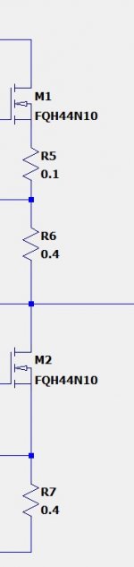
This should get you where you want to be.
If you desolder the source pin from the pcb (ie electrically disconnect source pin from pcb) you could then add a 0.1 Ohm resistor directly to source pin, then solder other end to pcb. Then add 0.4 Ohm in the usual location to achieve the same result attached.
This will get you in the ball park for the kind of distortion you want
Just reduce to 0.05 Ohms if it's still too much of a good thing.
Attachments
Last edited:
Hi James,
I would expect some of the change in the sound by adding those big caps on the output of the supply is due to the very nature of the Kemet ALS70 caps (previously known as BHC) and are regarded as one of the 'best sound' for midrange - a variation on these were the Slit Foils and the 4 pole ones built for DNM Audio but not made anymore.
Mundorf and SuperCap 4 pole caps are available (and maybe others) but not the same 'sound'.
I'm a bit surprised at the high prices of these big caps these days - the Rifa 169s, and the similar Epcos capacitors are also up there too.
Correction on the source resistors I'm using – these are the Bourns PWR221T-30 series, 30W, 1%. I'll order a set of 400 mΩ, 100 mΩ and 50 mΩ to experiment with when I have more free time. My original attempt at connecting the low side of C1 to the OUT node definitely produced too much of a thing. I suspect small tweaks will be the way to go, given how good the amp sounds already.
I had the Kemet ALS70 caps left over from my ACA-220 builds, so they were already nicely broken in. The 24 mF values were replaced by 36 mF as the initial stage in a CRCRC linear supply that I built into the old Hafler chassis. I still like tweaking those amps on occasion, just for the fun of it. They are good for showing what can, and can not, be done with power supplies. My last work with those actually left me better prepared for the work I'm now doing on the F6.
I had the Kemet ALS70 caps left over from my ACA-220 builds, so they were already nicely broken in. The 24 mF values were replaced by 36 mF as the initial stage in a CRCRC linear supply that I built into the old Hafler chassis. I still like tweaking those amps on occasion, just for the fun of it. They are good for showing what can, and can not, be done with power supplies. My last work with those actually left me better prepared for the work I'm now doing on the F6.
Compare curves of Id vs Vgs.
IRFP150 will show steeper curves ie greater transconductance.
This is a good thing to have in a single gain stage amp.
Would I be correct in saying that I could stick with the stock 5v1 zener (rather than increasing as recommended) for biasing the IRFP150 as it will put through more current for a given Vgs so should bias no worries? (appears we get about 2x current for a given Vgs?)
Any disadvantage in using the IRFP150 over the IRFP250 - there are always trade-offs... (Noting my 4 Ohm speaker load) I see it has almost double the capacitance - so I guess that will increase high frequency distortion?
So is the trade-off more drive but more distortion? A worthy trade or not..

Thank you
- Home
- Amplifiers
- Pass Labs
- F6 Amplifier