Well, to my thinking why would you go to the trouble of having different source resistors if they don't do anything (with the diy schematic and pcb). As I have said people including myself mentioned the sound as dull and lifeless, I think my Aleph J sounds much better,it was a disappointment when I first heard my F6. I think its great that we may have better sound from all this.Is it?
The diyAudio F6 PCB was made to the schematic provided by Nelson when asked for one, specifically, this -
Note that the capacitor is attached directly to the source of the Mosfets.
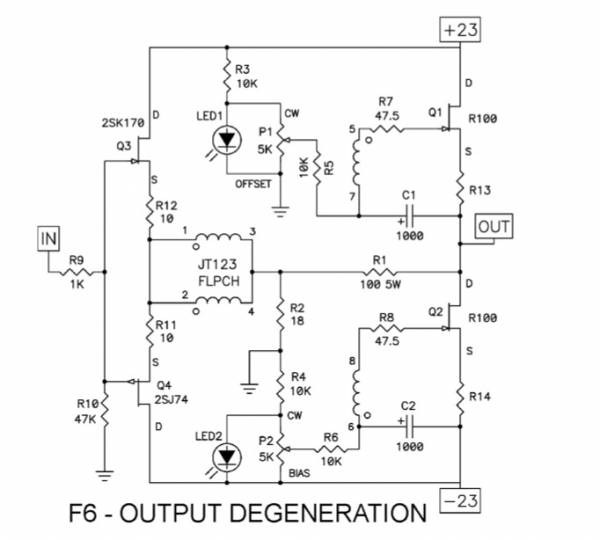
Yes, it does differ from the "Output Degeneration" schematic from the presentation at BAF '13 -
If the PCB has an error different than that, I'll happily look into it.
If one wants to connect the caps to the 'bottom' of the source resistors, a simple flying lead will be quite easy if one wants to try.
Is it?
The diyAudio F6 PCB was made to the schematic provided by Nelson when asked for one, specifically, this -
Note that the capacitor is attached directly to the source of the Mosfets.
Yes, it does differ from the "Output Degeneration" schematic from the presentation at BAF '13 -
If the PCB has an error different than that, I'll happily look into it.
If one wants to connect the caps to the 'bottom' of the source resistors, a simple flying lead will be quite easy if one wants to try.
The pcb matches perfectly the schematic in your build thread. So can't complain about that.
It just does not have the tweaking ability as described by Nelson in his F6 article the way it is.
I'm certain some people may prefer it exactly the way it is.
It's not what I "personally" had hoped for. I'm just one person, so probably really doesn't matter if I am a little disappointed.
It can be rectified with pcb mod. If people want to try it then they certainly can do that.
Have you looked at phase changes if the resistor values are changed?
Yes I did, the 2nd changes about 4 degrees, no change of 3rd. This is going from 0.57 to 0.47 ohms. This is with my original sim based on the diy board schematic.
Unfortunately I didn't get on the group buy.I would suggest the R100, personally, but to each his own.
However I noticed Infineon have some SiC mosfets with 0 tempco. They should be able to be used without source resistors. Then just choose devices with differences in transcoductance.
the easiest would be just to jumper the Sourceresistor(–holes), and go from each outputbound hole with resistors to output?
Damned, don´t have the solderstation at home, but supercurious to hear report🙂
st.
Damned, don´t have the solderstation at home, but supercurious to hear report🙂
st.
the easiest would be just to jumper the Sourceresistor(–holes), and go from each outputbound hole with resistors to output?
Damned, don´t have the solderstation at home, but supercurious to hear report🙂
st.
no, just for one side, look at the schematic u dumb😀
Well I have finished re routing the capacitor negatives to allow degeneration. Re biased etc. The sound stage is much more spread out and instruments placement is easier to pick out. The sound is not "in your face" anymore. It sounds like my Aleph J but with better bass, fantastic. The bass is not as boomy and overwhelming as before, much better integration. I would say any one that has these boards would do themselves a favor and do the mod, don't take my word, do it and you will see for yourselves.
btw, admit not knowing what the often used term degeneration means, can somebody hint me to an explanation?
😕😕

😕😕
btw, admit not knowing what the often used term degeneration means, can somebody hint me to an explanation?
😕😕
It's resistance (or reactance) in the source (or emitter if BJT) of the device. Most people think of it as "local negative feedback" as it will linearise the device (within limits).
Try these links for a more complete explanation:
http://en.wikipedia.org/wiki/Common_source
http://en.wikipedia.org/wiki/Common_emitter
http://www.colorado.edu/physics/phys3330/phys3330_fa06/pdfdocs/AN102FETbiasing.pdf

I was waiting to see if Papa would comment on the changes mentioned with the 1000 uh connection point and when he does not comment it usually means he has nothing to add. He just may not have seen the post though. I find it interesting what some have found and it may be worth a try for me to see the difference. It shows we have intelligent minds willing to try something different. It is not a hard change to make and change back if you do not see any difference or do not like the change.
I believe Mike Mazzola (Semisouthfan) still has some R100s.
I was wondering why for some the F6 was dull. Never my observation with those I have listened to ( point to point , TeaBag boards, buzzforb's Funny). Nice catch oreo382
I was wondering why for some the F6 was dull. Never my observation with those I have listened to ( point to point , TeaBag boards, buzzforb's Funny). Nice catch oreo382
I was waiting to see if Papa would comment on the changes mentioned with the 1000 uh connection point and when he does not comment it usually means he has nothing to add. He just may not have seen the post though.
He has already said much on this subject in the PDF of his talk linked by pico a few posts back. The original version with R100s did not include degeneration and the cap was connected directly to the FET's source. EUVL provided an alternate schematic with variable degeneration: the cap could be connected to the source, to the output, or to any point of a resistor divider in between. All variations are perfectly valid and simply result in a different 'tuning' of the second harmonic content.
I believe Mike Mazzola (Semisouthfan) still has some R100s.
I was wondering why for some the F6 was dull. Never my observation with those I have listened to ( point to point , TeaBag boards, buzzforb's Funny). Nice catch oreo382
Actually it was 2picodumbs that identified the solution.I was just stumbling along trying different parts to see what would affect the harmonics of the amp.
How is the First Watt F6 with 240's configured?
That is something I have been wondering about as well. Maybe Nelson will let us know.
I believe Mike Mazzola (Semisouthfan) still has some R100s.
I was wondering why for some the F6 was dull. Never my observation with those I have listened to ( point to point , TeaBag boards, buzzforb's Funny). Nice catch oreo382
I have been running SJEP120R100's, purchased from zhoufang back in 2010, in the Tea-bag white PCBs. Ran that for about a month then I switched the outputs for matched pairs from Mike Mazzola with matched transfer curves.
The change in sound was very noticeable! Better, deeper sound staging.
Width of stage the same.
Tone and texture/harmonic information of instruments, both acoustic/orchestral and electronic/pop/artificial staging type recordings. This was top to bottom of the frequency range.
I have the F6 DIYAudio store pcbs and matched mosfets on the way from Hannes Allmaier. It will be interesting to compare the JFet to Mosfet
versions.
...and no, neither version of the F6 I've tried so far sounded dull. I would say the F6es sound is more refined and not edgy like the F5 with Fairchild Mosfet outputs. Like a veil of hash was removed.
Just my 2 cents.

- Home
- Amplifiers
- Pass Labs
- F6 Amplifier