I still have 4 PCBs left to those lucky ones who wish for a low distortion F6.
18$/pair + shipping...
ALL SOLD!
Thanks to everybody who bought!
Good choice... ;-)
BR:C
PS: THD 0.009% @ 2A bias, but you need massive heatsinking...
Bias w/o source resistors
I am going to experiment with a F6 with no output degeneration - no source resistors on the SS R100s
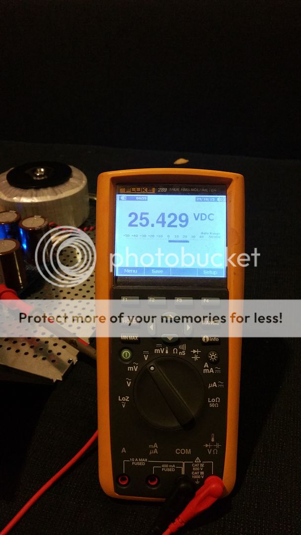
My PSU is a CLC - unsure of DCR of the inductors - so I can't take voltage drop there.
If I set Vgs at 1.2V using bias pot does this give me 1.5A bias?
Thanks
Bob
I am going to experiment with a F6 with no output degeneration - no source resistors on the SS R100s
My PSU is a CLC - unsure of DCR of the inductors - so I can't take voltage drop there.
If I set Vgs at 1.2V using bias pot does this give me 1.5A bias?
Thanks
Bob
I am going to experiment with a F6 with no output degeneration - no source resistors on the SS R100s
My PSU is a CLC - unsure of DCR of the inductors - so I can't take voltage drop there.
If I set Vgs at 1.2V using bias pot does this give me 1.5A bias?
Thanks
Bob
Measure DC resistance of inductors, very important to know that, otherwise you can't set the bias.
Use a voltage like 10 volts or so, use a known resistor in series, like a 10 ohm or so at 1% or better. Measure the voltage drop on inductor and resistor, then do the math.
Rush
I am going to experiment with a F6 with no output degeneration - no source resistors on the SS R100s
My PSU is a CLC - unsure of DCR of the inductors - so I can't take voltage drop there.
If I set Vgs at 1.2V using bias pot does this give me 1.5A bias?
Thanks
Bob
With no source feedback, the drain current will depend heavily on the transfer curve of the actual devices. VGS = 1.2 V will likely have to be adjusted for your matched pair due to the range of threshold voltage in normal production, which varied at least 1 V +/- 0.25 V. I see this type of distribution (and more) over my inventory when matching parts.
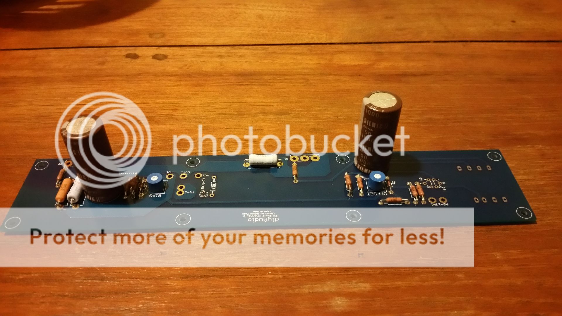
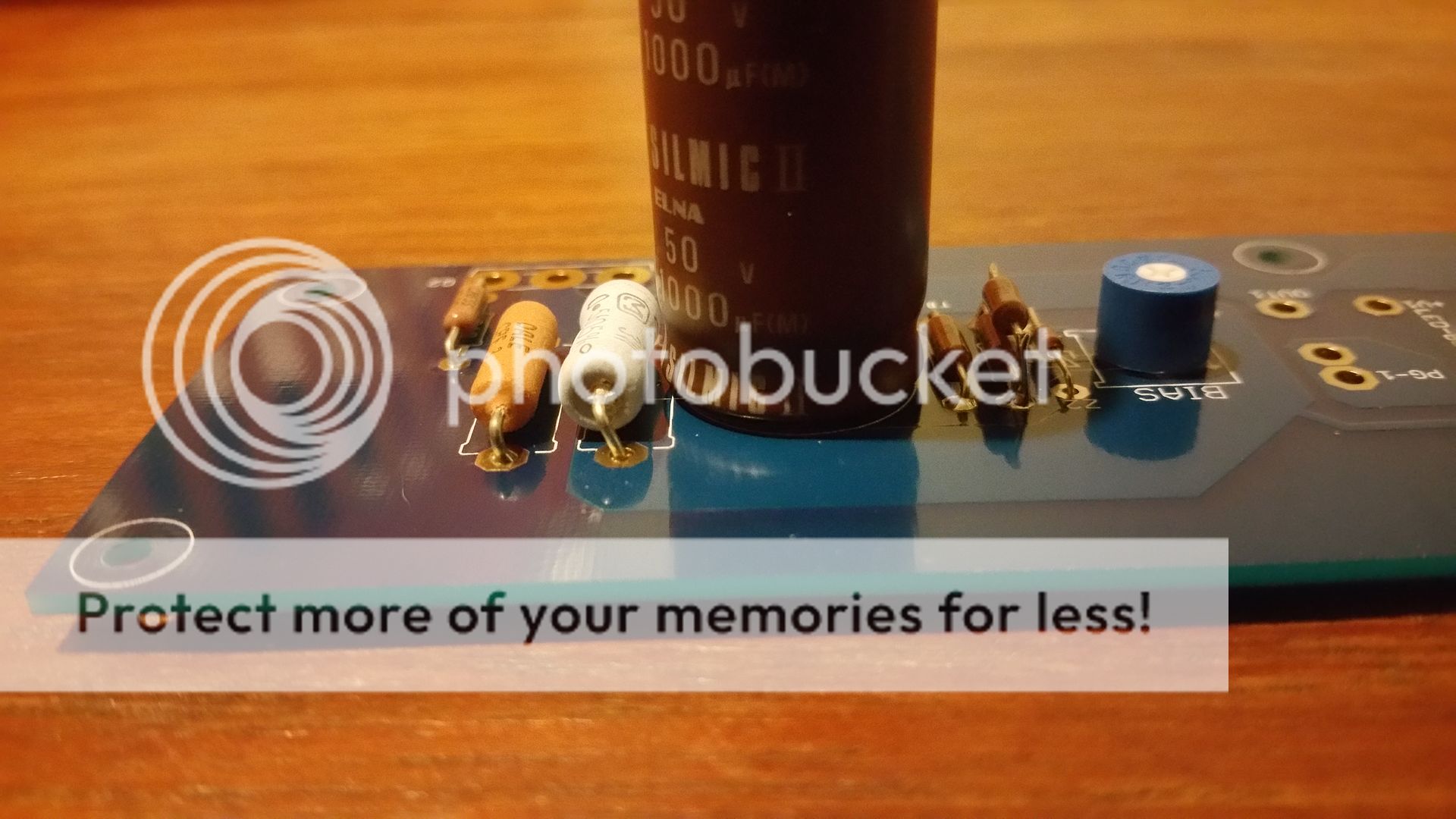
There is 2mm clearance between power resistors and pcb. Only dissipating around 0.7W, should be ok. The heat coming off the heatsink is probably more than the resistor.I would raise those white resistors off the board some more but they will probably be fine where they are at but why take a chance. With longer leads you could bend it away from the capacitor too. Good start on your F6.
Last edited:
As one of the Mob movies says when someone is arrested, "I don't think he will talk he is a stand up guy, another says me too no way he will talk. Then the Godfather says why take a chance." If there is no problem on fire up you are probably right but if it gets too hot it is going to take that capacitor with it.
As one of the Mob movies says when someone is arrested, "I don't think he will talk he is a stand up guy, another says me too no way he will talk. Then the Godfather says why take a chance." If there is no problem on fire up you are probably right but if it gets too hot it is going to take that capacitor with it.
Yeah I'm a big believer in Murphy's law.
")
I'll be sure to check the heat coming off the resistor, if it's less than 50 degrees Celsius, I'm not going to worry about it.
Last edited:
As one of the Mob movies says when someone is arrested, "I don't think he will talk he is a stand up guy, another says me too no way he will talk. Then the Godfather says why take a chance." If there is no problem on fire up you are probably right but if it gets too hot it is going to take that capacitor with it.
The "myth of Omerta".....
raghhhhhhh, today my mosfets will arrive for finishing the F6. I read somewhere that matching is not "really" required, but since i ordered 25 irfp240 i could do some.
Could you please give me a hint what to match? (and can i do it with a 9V battery )
-for the 15 V DC test circuits as suggested in the FW-papers i could make little 12V transformer-bridge-say 12000 uF supply?
Sorry, but it was all about casebuilding the last days, and even the matching doesn´t really come as a surprise, i may have the common "treshhold resistance" when you are not too much into electronics.
As for the VGS, is threshhold important (the 4.-something Volts when conduction begins, or the ratio V vs I ?
thanks (i know its basic)
stefan
(btw, its up in the galery)
Could you please give me a hint what to match? (and can i do it with a 9V battery
)-for the 15 V DC test circuits as suggested in the FW-papers i could make little 12V transformer-bridge-say 12000 uF supply?
Sorry, but it was all about casebuilding the last days, and even the matching doesn´t really come as a surprise, i may have the common "treshhold resistance" when you are not too much into electronics.
As for the VGS, is threshhold important (the 4.-something Volts when conduction begins, or the ratio V vs I ?
thanks (i know its basic)
stefan
(btw, its up in the galery)
finally (matching)
i wasn´t able to find any 12V trafo to build up the 15 V test rig for mosfet testing, but the parts were laying around and i felt like nettle rash to finish the amp, so i went with my little chinese device tester that gave me Vt (what i interpreted as V threshhold). I found four devices with 3500 mV Vt and put them in.
I´ll build the 15V testing-rig soon and will check if there is a correlation of Vth and VGS at all, at least it is not about parallel devices and enequally shared current, it is "just" about distortion as far as i understood.
quick listening:
when i hook up the amp to my cheap open baffles in studio i immediately was aware of the nicely deeper soundstage compared to F5.
today i hooked it up to my speakers at home and my first impression is a little a disappointment about the tonal balance being quite dark. I expectet it being more on the bright side, since there was a guy here who thought about tweaking his crossovers. Mhmmm could it be because of my amateurisch "device matching"? supposingly not.
however the bass itself is veery nice, lotsa colour.
could i try to change R1(.56) to R.47 to have more H3 for a quick listening test?
thanx,
stefan
i wasn´t able to find any 12V trafo to build up the 15 V test rig for mosfet testing, but the parts were laying around and i felt like nettle rash to finish the amp
, so i went with my little chinese device tester that gave me Vt (what i interpreted as V threshhold). I found four devices with 3500 mV Vt and put them in. I´ll build the 15V testing-rig soon and will check if there is a correlation of Vth and VGS at all
, at least it is not about parallel devices and enequally shared current, it is "just" about distortion as far as i understood.quick listening:
when i hook up the amp to my cheap open baffles in studio i immediately was aware of the nicely deeper soundstage compared to F5.
today i hooked it up to my speakers at home and my first impression is a little a disappointment about the tonal balance being quite dark. I expectet it being more on the bright side, since there was a guy here who thought about tweaking his crossovers. Mhmmm could it be because of my amateurisch "device matching"? supposingly not.
however the bass itself is veery nice, lotsa colour.
could i try to change R1(.56) to R.47 to have more H3 for a quick listening test?
thanx,
stefan
, so i went with my little chinese device tester that gave me Vt (what i interpreted as V threshhold). I found four devices with 3500 mV Vt and put them in.
I´ll build the 15V testing-rig soon and will check if there is a correlation of Vth and VGS at all
I recently did this and posted results in F4 thread. I got very good correlation with irfp240 devices matched to within 0.02V at threshold and at higher operating currents
could i try to change R1(.56) to R.47 to have more H3 for a quick listening test?
thanx,
stefan
That is definitely worth playing with but unlikely to solve your issue completely. It definitely should sound different and maybe more too your liking.
I would be tempted to try adding more feedback, that will increase bandwidth and should brighten up the amp. You could add another 100 Ohm resistor in parallel (for 50 Ohms) just for testing purposes, then start tweaking further after you have performed a listening test.
Last edited:
hi Pico, thanks a lot for sharing that. i´ll nevertheless try to verify the VGS in a proper set when i have more time.
For tonal balance in my system i for now tweaked a little in the speaker crossover, but shurely will fiddle on R1 (SR) and the R3 (feedback).
I wasn´t aware that i can just do that so easily.
exhausted now from setupchanging all the day
cheers
stefan
For tonal balance in my system i for now tweaked a little in the speaker crossover, but shurely will fiddle on R1 (SR) and the R3 (feedback).
I wasn´t aware that i can just do that so easily.
exhausted now from setupchanging all the day
cheers
stefan
- Home
- Amplifiers
- Pass Labs
- F6 Amplifier