Your pcb accepts two Jensens. a possible pathway to use both and increase OLG if desired.I did some different measurements today: Closed-loop and open-loop rolloff and open-loop gain. The rolloff frequencies were estimated from the oscilloscope time base.
Closed-loop rolloff: Gain=6, 1.3A bias, Cfb=10nF compensation cap
-3dB 5.5 div @ 1us/div = 182 kHz (LTSpice predicts 141 kHz)
-6dB 8 div @ .5us/div = 250 kHz (LTSpice predicts 234 kHz)
Open-loop rolloff
-3dB 6 div @ 2us/div = 83 kHz
-6dB 8.6 div @ 1us/div = 116 kHz
Open-loop gain measurement: 1kHz sine wave, 2 volt peak output
Fluke DMM measurement
32mV RMS input for 2V peak output
Oscilloscope measurement
4.5 div P-P @20mV/div = 90mV P-P
0.5*0.090*sqrt(0.5) = 32mV RMS - agrees with Fluke
Open-loop gain = 2.0/0.032 = 62.5 (LTSpice predicts 70)
Thanks generg. K3 is almost flat at -105dB, and K2's behaviour is as you said above. A single point measurement [say at a 1 KHz fundamental] will never tell the full story.Hi Antoinel,
Look here http://www.diyaudio.com/forums/pass-labs/216616-f6-amplifier-438.html#post3517149
First picture there you can see what lhquam said about k2 changing over the frequency and the difference of behaviour of k2 and k3 over the frequency band.
")
Here's a question. K2 and K3 are real signals which have amplitude, bandwidth and phase. Can one pull these analog signals out of the THD analyzer and manipulate electronically [invert phase, amplify] and then listen to them separately from the fundamental frequencies in music; at least via headphones?
Best regards
I am not too worried about the voltage gain. Yes, it means less feedback, but what I am exploring is ways to further lower the distortion without more feedback.Your pcb accepts two Jensens. a possible pathway to use both and increase OLG if desired.
Another idea is to use two bifilar Jensens, completely separating the drive to the two output FETs.
No, with cascoding, the gain is slightly lower. The differences between the cascode and non-cascode plots are due to
Thanks for that... Just to be clear .. I was referring to the cool olg measurements you made above. I like to try and understand things from first principles and these types of exercises are a great help to me in that regard.
Its not intuitive to me why cascode olg would be lower than non cascode so will need to think about it a little. The gain or signal fet *should* have some gain >1.0 and the common gate fet has gain approx gmRL so the product should be more than single fet gmRL. Or thats how it seems to me given my poor knowledge of cascodes at the mom. Time for me to think more and talk less I guess ... Anyway it's late here so maybe one of these might help
The common-gate (cascode) FET provides no voltage or current gain, it just establishes the drain voltage of the drive FET. The current thru the cascode FET is the same as that of the drive FET. The voltage at the output node is the difference of the currents thru the FETs times the load resistance.
Thanks generg. I love to be creative. For this experiment, Mr. Pass beat me to it in his article "Mosfet Citation 12" under a title like "let the amp analyze itself" [used a stereo amp]. Use a music signal rather than that of a function generator. The distortion emerges from the power output of one channel, and can be presented to a scope or a pair headphones with a possible need of preamplification.you are a very creative guy... funny idea!
I do not know how to do this.....
Best regards
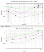
Switched the output drive FETs to FQA19N20C and FQA12P20. Here are OPENLOOP THD sweeps. The output offset voltage is much more stable than with the FQA28N15 and FQA36P15 drive FETs. It probably means that the added stabilization resistors can be increased in size, thus reducing their influence on bias current when the rail voltages change.
Attachments
Yeah, but I get an openloop gain of only 28 with them biased at 1.3A. Their transconductance is much lower than the FQA28N/36P FETs. I guess it depends on the distortion levels you want.Nelson uses these FETs in his M2 too....
Maybe your firm belief in the Pass Doctrine/Philosophy of a simple design is holding you back from pursuing additional complexity needed to change the status quo.Yeah, but I get an openloop gain of only 28 with them biased at 1.3A. Their transconductance is much lower than the FQA28N/36P FETs. I guess it depends on the distortion levels you want.
I am pursuing the additional complexity of cascoding the output FETs and using complementary output FETs. The challenge is to push the limits of that twist on the original F6 design.Maybe your firm belief in the Pass Doctrine/Philosophy of a simple design is holding you back from pursuing additional complexity needed to change the status quo.
The challenge shows and I feel it in your posts. Your growing knowledge base will without doubt present the best solution.I am pursuing the additional complexity of cascoding the output FETs and using complementary output FETs. The challenge is to push the limits of that twist on the original F6 design.
I see your cascoding approach, and use of complementary output FETs a benefit to advance the performance of diyF6; rather than a burdensome complexity. Teaser F6CC is a simple cascoded amp. I wish there is word or adjective in lieu of "complexity" to invoke performance improvements [by using more components] rather than provoking its literal meaning.
Amp philiosphy. ZM is clearly behind this.
I believe Nelson might have stated in one of his articles tha if we are looking for vanishing distortion or ultimate measured performance, look to op amps. May be misquoting. If this is what you are after, the last amp you should build is the F6, but damn if it doesn't sound good....especially with a nice glass of wine and a little bit of self deception.
I believe Nelson might have stated in one of his articles tha if we are looking for vanishing distortion or ultimate measured performance, look to op amps. May be misquoting. If this is what you are after, the last amp you should build is the F6, but damn if it doesn't sound good....especially with a nice glass of wine and a little bit of self deception.
Last edited:
The F6 really does push the limits for a single stage amp. (It is a single stage amp assuming that the input follower isn't really essential if the source impedance is low enough).Amp philiosphy. ZM is clearly behind this.
I believe Nelson might have stated in one of his articles tha if we are looking for vanishing distortion or ultimate measured performance, look to op amps. May be misquoting. If this is what you are after, the last amp you should build is the F6, but damn if it doesn't sound good....especially with a nice glass of wine and a little bit of self deception.
I am about to finish my bench tweaking, build a 2nd channel, power them with the chassis containing the power supply from my first F5 build, and take it to my listening room for evaluation. Unfortunately, I have not yet built a chassis for convection cooled FirstWatt size amps. That is probably next on my list.I think you are right. IT is really amazing the performance that is achieved with such a imple topolgy. I am interested to hear the F6CC and how it fits into the scheme of things. I am kinda on a cacsode fetish recently, anyway.
Do mono locks or make room for dual mojo. It is a significant difference, IMO. Went to a lot of trouble with second F6 build to make everything match really well, with one exception, the PSU. I did dual mono with one difference, one PSU board has 8-22mF the other has 8-20mF. You can clearly distinguish the channels. I know there is a clear technical difference, but I bet most would say you can't hear 8mF per rail in a PSU of this size.
Last edited:
Is the difference due to the amplifier channels, the power supplies, or the left/right room acoustics? There are a lot of possible explanations for the perceived differences.Do mono locks or make room for dual mojo. It is a significant difference, IMO. Went to a lot of trouble with second F6 build to make everything match really well, with one exception, the PSU. I did dual mono with one difference, one PSU board has 8-22mF the other has 8-20mF. You can clearly distinguish the channels. I know there is a clear technical difference, but I bet most would say you can't hear 8mF per rail in a PSU of this size.
- Home
- Amplifiers
- Pass Labs
- F6 Amplifier