I have been experimenting (both Spice and actual testing) with amplifier circuits using NO AC degeneration and cascoding to see if I can significantly reduce the 3rd harmonic (and 2nd also). The problem is to achieve DC bias stability without having AC degeneration. One approach is to use very large capacitors (0.5Farad or larger) across the source resistors. That appears to work fine except at frequencies below about 100 Hz.
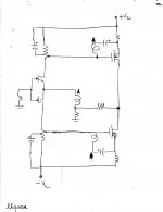
Here is a circuit using the Jensen transformer and F6 style bias, but using both NMOS and PMOS output FETs and cascoded outputs. A similar design using only NMOS outputs has much higher 2nd harmonic due to the interwinding capacitances and the large AC swing on the upper transformer secondary.
Spice simulations looks good. The next step is to build it and test.
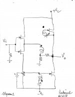
lhquam. I studied your schematic. It inspired me to embody the Jensen transformer of diyF6 in that of F5; a hybrid schematic of sorts. The modified schematic is attached. It is simplified by excluding cascoding. Here are its benefits.
- DC servo capability to null voltage offsets at the output
- Feedforward a portion of the inverted signals from the front end to the gates of the MOSFETs. This will improve the amp's high frequency response before applying Pass Feedback. Recall that in diyF6 the frequency response begins to roll off at 5 KHz; because the output stage amplifies the interwinding capacitance in the transformer to shunt the higher frequencies.
Best regards
Attachments
lhquam. The attached schematic is that of a modified diyF6. It implements the approach suggested above. Clearly, diyF6 has an excellent stability of its DC output voltage as several DIYers talked about in recent threads.
Best regards
- The inverted error signal [in part or fully] from the front end P-JFet is fedforward to the gate of the lower R100A. This is expected to increase the frequency response of this amp [beyond 5KHz] prior to the application of Pass Feedback. Clearly a benefit.
- Bias to the lower R100A emanates and is managed by the front end.
Best regards
Attachments
lhquam. The attached schematic is that of a modified diyF6. It implements the approach suggested above. Clearly, diyF6 has an excellent stability of its DC output voltage as several DIYers talked about in recent threads.
Some of you may dislike [or like] this approach; because the output stage is now deliberately asymmetric. Matched R100A are not required either; which entrains asymmetry too.
- The inverted error signal [in part or fully] from the front end P-JFet is fedforward to the gate of the lower R100A. This is expected to increase the frequency response of this amp [beyond 5KHz] prior to the application of Pass Feedback. Clearly a benefit.
- Bias to the lower R100A emanates and is managed by the front end.
Best regards
I am not sure I understand the implications of the feed-forward. Have you done any simulations or construction of either scheme?
.......
Here is a circuit using the Jensen transformer and F6 style bias, but using both NMOS and PMOS output FETs and cascoded outputs. A similar design using only NMOS outputs has much higher 2nd harmonic due to the interwinding capacitances and the large AC swing on the upper transformer secondary.
Spice simulations looks good. The next step is to build it and test.
Hi lhquam,
Could you please say some words why with NMos only we have higher k2 and more swing on the upper side?
")
How good is the quality of the signal from of an old function generator or one of those inexpensive digitally synthesized ones?
If your computer is good enough to use as a source then it should be good enough to be used as a generator =)
Feedforward in both schemes generates a current source amp [prior to Pass Feedback] which has a bandwidth that is wider than in its absence. Thus, the error correction elements do not or are not inclined to invest open loop gain to correct. An intrinsic wide bandwidth is already there! May also view feedforward as bootstrapping the outputs of the secondary windings.I am not sure I understand the implications of the feed-forward. Have you done any simulations or construction of either scheme?
I have not done simulations or builds. I hope that this will not mean to you or others that I am full of hot air or other stuff ! My simulation is old style:
- Write a schematic
- Inspect it for errors; does it make sense?
- Its expected audio value?
I wonder whether STASIS technology was invented by LTSPICE simulations?
Best regards.
Thanks Zen Mod. 6L6 assigns a sonic benefit to the transformer. It is the Belle of diyF6.#4381 - supercool
Best regards.
I showed similar ideas in earlier posts; by using BA3 front end. Then, the question at hand was how will Mr. Pass bias the R100As. The ideas were proposed as possible solutions. Now, I can see additional and well-defined value in them.Seems familiar.
Best regards
If your computer is good enough to use as a source then it should be good enough to be used as a generator =)
I suppose. I didn't think of using software. I was looking at one of those cheap DDS function generators on ebay for like $20.
Hi lhquam,
Could you please say some words why with NMos only we have higher k2 and more swing on the upper side?
When the upper FET is N-type, then its source and gate are both swinging (approximately) by the output voltage of the amplifier. Thus, both ends of the transformer secondary for the upper FET is also swinging approximately by the output voltage and coupled to the other windings by the interwinding capacitances. This coupling is asymmetric and contributes to the second harmonic increasingly with frequency.
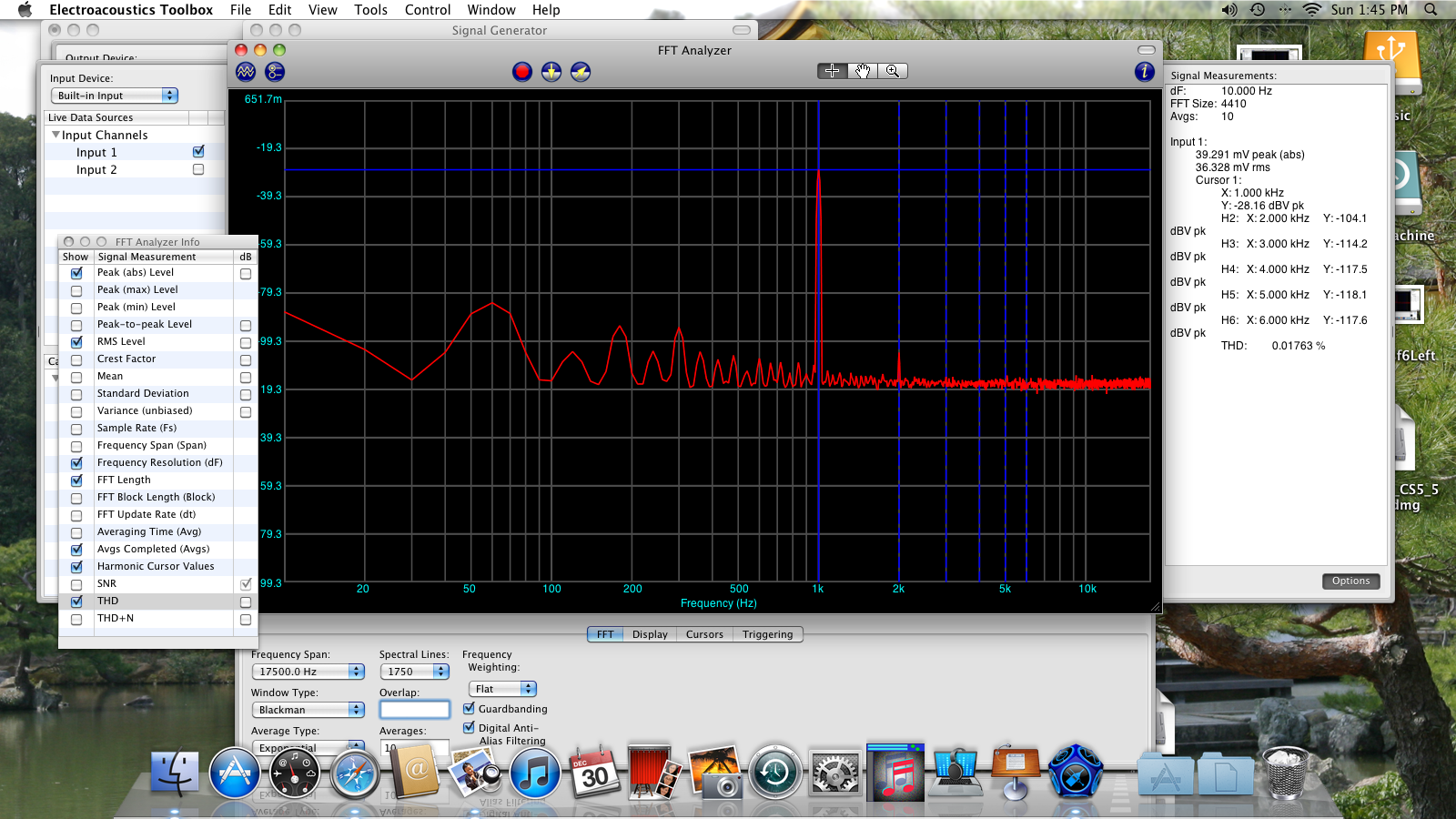
I found fairly high differences in the THD values of the different programs.
For instance my Mac program shows always smaller values than ARTA. But of course you can trim to lowest THD, even when the absolute value is not correct.
And even more important to me, the distortion spectra looks the same with all the programs! So you can adjust "your" sound.
@tea-bag and 6L6 I found a discrepancy between the graphs saying and the db number shown in the side window with Electroacoustics Toolbox. For instance I adjust the graph that k2 and k3 have the same level, but the dB numbers show different values and vice versa.
I checked with ARTA and Virtual Analyser and it seems that the graphs values are the correct one.
Can you help to find the reason?
I have some of the old screen shots.
This looks right I think.
http://www.diyaudio.com/forums/blog...6-clone-convertible-pcb-blog-jensenf6left.png
Last edited:
@lhquam and Zen Mod
Thank you for the explanations!
@Tea-Bag, yes, your pictures are good, no deviation. Nevertheless I beg you and 6L6 when your measuring again to adjust for fun k2 and k3 at the same level by graph and by numbers and tell me if you see a difference please.I will post a picture of my deviation tomorrow.
Perhaps these posts are somewhat off-thread, but unless someone suggests a new thread, here they are:
Here are some Spice simulation resulted for the schematic shown in post #4367 http://www.diyaudio.com/forums/pass-labs/216616-f6-amplifier-437.html#post3516867. The plots are:
I will perform similar simulations without cascoding.
Here are some Spice simulation resulted for the schematic shown in post #4367 http://www.diyaudio.com/forums/pass-labs/216616-f6-amplifier-437.html#post3516867. The plots are:
- Harmonics vs. frequency at 1 watt into 8 ohms.
- Harmonics vs. frequency at 10 watts into 8 ohms.
- Harmonics vs. power at 1 kHz.
- Harmonics vs. power at 7 kHz.
I will perform similar simulations without cascoding.
Perhaps these posts are somewhat off-thread, but unless someone suggests a new thread, here they are:
Here are some Spice simulation resulted for the schematic shown in post #4367 http://www.diyaudio.com/forums/pass-labs/216616-f6-amplifier-437.html#post3516867. The plots are:
Note how H3 remains rather constant vs. frequency and H2 increases nearly linearly with frequency above 1 kHz. If one were to build a bridged ( balanced) amplifier from this in order to cancel most of H2, the result would even more impressive.
- Harmonics vs. frequency at 1 watt into 8 ohms.
- Harmonics vs. frequency at 10 watts into 8 ohms.
- Harmonics vs. power at 1 kHz.
- Harmonics vs. power at 7 kHz.
I will perform similar simulations without cascoding.
- Home
- Amplifiers
- Pass Labs
- F6 Amplifier