Succeeded to use ARTA and STEPS with Windows 64 the last hours.....
Very nice to see the distortion over the whole audio band. Interesting when I trimmed k2 down to the minimum at 1kHz and k3 was clearly dominant (10dB), k2 kept lower only up to 2 kHz , then k2 was no more paralle,l but began to rise and finally surpassing k3 at around 5kHz.
When I adjusted a 6 or 10 db dominance of K2 at 1kHz, this dominance kept parallel over the audio band....
Tomorrow I will post some pictures...
")
Very nice to see the distortion over the whole audio band. Interesting when I trimmed k2 down to the minimum at 1kHz and k3 was clearly dominant (10dB), k2 kept lower only up to 2 kHz , then k2 was no more paralle,l but began to rise and finally surpassing k3 at around 5kHz.
When I adjusted a 6 or 10 db dominance of K2 at 1kHz, this dominance kept parallel over the audio band....
Tomorrow I will post some pictures...

"But Jim, I don't have a distortion analyzer! How can I measure and set the pots?"
That is painfully simple, once the secret is let out. (Thank you Generg and Tea-Bag)
Make one of these - Electronic Equiptment - DIY soundcard scope probe
Connect it across a 4- or 8-ohm resistor on the output of your amp. Feed your amp a nice 1KHz sinewave. Adjust the pot so that you send no more than a 1V signal to the computer input.
Plug into your computer mic input and use a FFT program like this audioTester or this SignalScope
You will have resolution that was only dreamed about 30yr ago, and can adjust the distortion visually, looking at the 2nd and 3rd harmonic peaks on the FFT plot.
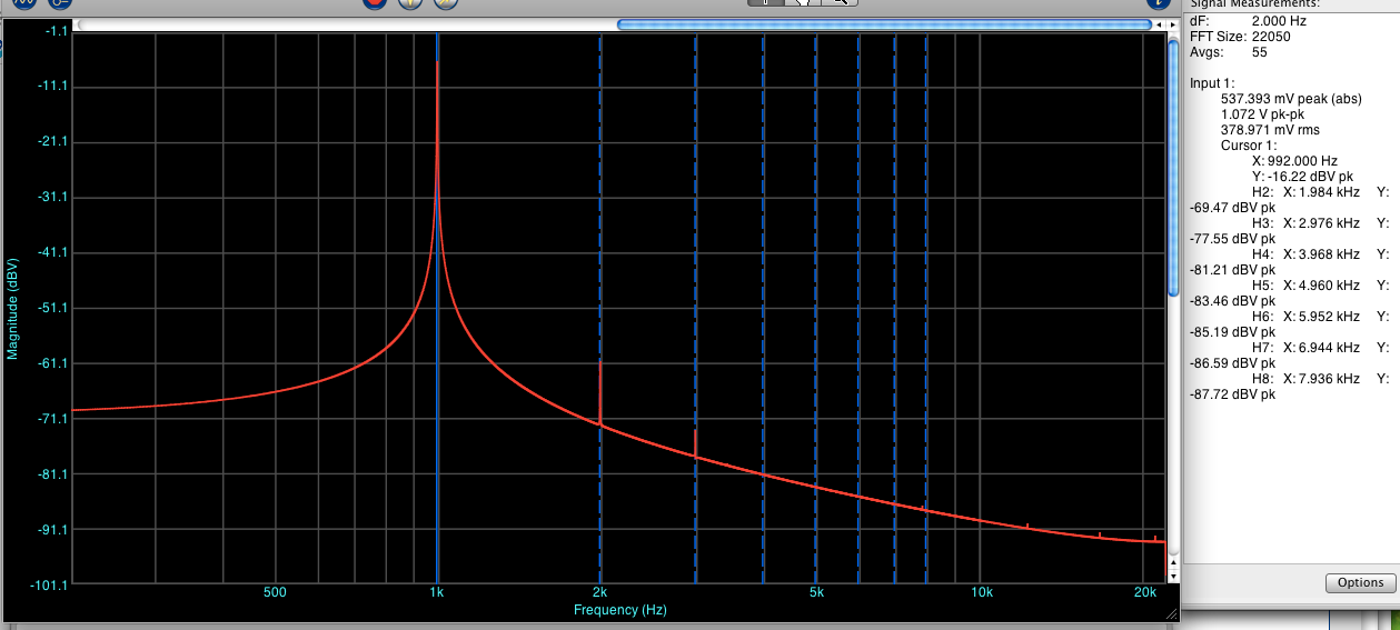
Taken from another thread about bias vs. distortion, but cleanly shows the fundamental at 1K, and the harmonic peaks at 2 and 3K.
As Papa says;
What is a decent signal generator for short money?
There is a simple battery-powered DIY schematic that I saw somewhere... Let me see if I can dig it up.
FWIW, I bought a really nice old (mid-late 80's) B&K precision signal/sweep generator for $100 off Craigslist.
You can also use a soundcard for all this as well, most of them can output signals as well.
FWIW, I bought a really nice old (mid-late 80's) B&K precision signal/sweep generator for $100 off Craigslist.
You can also use a soundcard for all this as well, most of them can output signals as well.
I have been experimenting (both Spice and actual testing) with amplifier circuits using NO AC degeneration and cascoding to see if I can significantly reduce the 3rd harmonic (and 2nd also). The problem is to achieve DC bias stability without having AC degeneration. One approach is to use very large capacitors (0.5Farad or larger) across the source resistors. That appears to work fine except at frequencies below about 100 Hz.
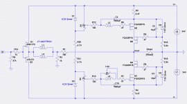
Here is a circuit using the Jensen transformer and F6 style bias, but using both NMOS and PMOS output FETs and cascoded outputs. A similar design using only NMOS outputs has much higher 2nd harmonic due to the interwinding capacitances and the large AC swing on the upper transformer secondary.
Spice simulations looks good. The next step is to build it and test.
Attachments
I thought it wasn't possible to tweak amplifiers without far better equipment?
If you can do it with a 50-yr old HP distortion analyzer, why not with a computer converting your signal into much better than 24/96, and then applying a whole bunch of floating-point algorithms to analyze that signal, in a way that wasn't possible for love nor money in the 70's?
Computers have become so ubiquitous and used for mundane purposes that most people forget that they can apply a whole bunch of math very easily to extremely complex signals. You just need to get the signal into the computer for the (very sophisticated) software to do it's magic. I use the microphone input on a 6-yr old mac to get this into the computer, not a dedicated soundcard...
The tweaking is simple even with basic tools, but don't think that this is all that basic. The trick is being able to see it (the distortion) in order to tweak it. It can't be done by ear.
Here is an oscillator schematic - audio sine wave generator
It seems very nice.
I'm still looking for the one I'm thinking of... give me a bit.
I just thought it was discussed in the F5 thread years ago that a homebuilt amplifier would never sound as good as a factory made one. Some have even compared.
Here are some options -
Online Tone Generator - Free, Simple and Easy to Use.
Online Tone Generators - Highest Quality
Audio Test Oscillator
And I will happily loan my B&K for a week or so to anyone who promises to 1) be nice to it, 2) pay shipping. Heck - just ship it to the next guy who can make use of it. It will come back to me eventually...
Also, I bought some F5 boards last year from the store and questioned why the added P3 pot wasn't on the board yet.
http://www.diyaudio.com/forums/diyaudio-store/214004-f-5-boards-5.html#post3253715
http://www.diyaudio.com/forums/diyaudio-store/214004-f-5-boards-5.html#post3253715
 I may very we'll take you up on that offer at some point! Lot of <$30 boards from China/HK out there as well.
I found fairly high differences in the THD values of the different programs.
For instance my Mac program shows always smaller values than ARTA. But of course you can trim to lowest THD, even when the absolute value is not correct.
And even more important to me, the distortion spectra looks the same with all the programs! So you can adjust "your" sound.
@tea-bag and 6L6 I found a discrepancy between the graphs saying and the db number shown in the side window with Electroacoustics Toolbox. For instance I adjust the graph that k2 and k3 have the same level, but the dB numbers show different values and vice versa.
I checked with ARTA and Virtual Analyser and it seems that the graphs values are the correct one.
Can you help to find the reason?
for me new....
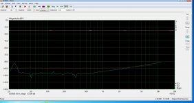
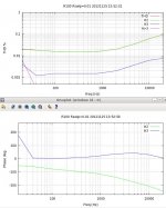
- BA-3 inputstage adjusted with P3 so that k2 is at minimum at 1kHz at 8R/1W... but this is only true for the range from 30Hz to 3KHz. From this point on k2 surpasses k3.
- the BA-3 input stage adjusted for k2 around 6db higher than k3 at 1KHz/8R/1W, you see the two curves keep parallel a long time...
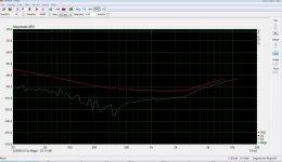
- last picture shows M2 clones distortion
may be old stuff for many of you...
Sorry I offer here the data of BA-3 inputstage and M2 clonetry but I hope other people will do the same with F6 and I am interested to see the similarities or differences. I must dig for Ihquams old measurements.
F6 is just out of the case and poor boy has only one case....
And it was Nelsons F6 gift that lead my attention finally to this point playing...the distortion tango....
k2 blue, k3 red...
- BA-3 inputstage adjusted with P3 so that k2 is at minimum at 1kHz at 8R/1W... but this is only true for the range from 30Hz to 3KHz. From this point on k2 surpasses k3.
- the BA-3 input stage adjusted for k2 around 6db higher than k3 at 1KHz/8R/1W, you see the two curves keep parallel a long time...
- last picture shows M2 clones distortion
may be old stuff for many of you...
Sorry I offer here the data of BA-3 inputstage and M2 clonetry but I hope other people will do the same with F6 and I am interested to see the similarities or differences. I must dig for Ihquams old measurements.
F6 is just out of the case and poor boy has only one case....
And it was Nelsons F6 gift that lead my attention finally to this point playing...the distortion tango....
k2 blue, k3 red...
Attachments

I just found one of lhquams old measurements of the F6 and you can see that k2 is very high above k3....I estimate around 20db higher...
http://www.diyaudio.com/forums/pass-labs/216616-f6-amplifier-311.html#post3256422
from my present knowledge I would say this will sound too dull, heay and masked..
so I understand fully that lhquam preferred the F5 much....
k2 maximum over k3 is for my ears around 12dB... of course very amp circuit dependent.
Attachments
- Home
- Amplifiers
- Pass Labs
- F6 Amplifier